background image

PARTS

Illustrated Parts - 39

Use only original Ventrac 

replacement parts.

REF. 

PART NO. 

DESCRIPTION 

QTY.

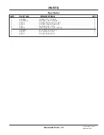
1   . . . . . . . . . 29.GF0001  . . . . . . . . . . . . . . . . .GREASE FTG, 1/4 SAE ST  . . . . . . . . . . . . . . . . . . . . . . . . . . . . . . . . . . . . . . . . . . . . . . . . . 2 

2   . . . . . . . . . 55.FB16016-2  . . . . . . . . . . . . . . .

BEARING, 2 BOLT FLANGE 1”

  . . . . . . . . . . . . . . . . . . . . . . . . . . . . . . . . . . . . . . . . . . . . . . 2 

3   . . . . . . . . . 50.0194  . . . . . . . . . . . . . . . . . . . .

ROLLER, END 5” DIA X 4” LONG

  . . . . . . . . . . . . . . . . . . . . . . . . . . . . . . . . . . . . . . . . . . . . 2 

4   . . . . . . . . . 64.1930  . . . . . . . . . . . . . . . . . . . .SPACER, REAR ROLLER END . . . . . . . . . . . . . . . . . . . . . . . . . . . . . . . . . . . . . . . . . . . . . . 4 

5   . . . . . . . . . 95.16  . . . . . . . . . . . . . . . . . . . . . .WASHER, FLAT 1 SAE . . . . . . . . . . . . . . . . . . . . . . . . . . . . . . . . . . . . . . . . . . . . . . . . . . . . . 4 

6   . . . . . . . . . 04.0025  . . . . . . . . . . . . . . . . . . . .

SNAP RING, EXT.1 SHFT .078 THK

  . . . . . . . . . . . . . . . . . . . . . . . . . . . . . . . . . . . . . . . . . . 2

7   . . . . . . . . . 99.SF0508   . . . . . . . . . . . . . . . . .

BOLT, SRF 5/16-18 USS X 1

  . . . . . . . . . . . . . . . . . . . . . . . . . . . . . . . . . . . . . . . . . . . . . . . . 4 

8   . . . . . . . . . 99.SF05   . . . . . . . . . . . . . . . . . . .NUT, SRF 5/16-18 USS . . . . . . . . . . . . . . . . . . . . . . . . . . . . . . . . . . . . . . . . . . . . . . . . . . . . . 4 

9   . . . . . . . . . 80.0388  . . . . . . . . . . . . . . . . . . . .ROLLER, REAR MS720  . . . . . . . . . . . . . . . . . . . . . . . . . . . . . . . . . . . . . . . . . . . . . . . . . . . . 1 


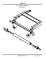
Rear Roller

Summary of Contents for MT720

Page 1: ...Operator s Manual Parts Drawings Side Discharge Offset Finish Mower Model MT720 Revised 11 15 17 09 10140 Rev 05 Original Operator s Manual ...

Page 2: ..._________________ Dealer ____________________________________________________________________________ Dealer Address _____________________________________________________________________ _____________________________________________________________________ Dealer Phone Number _______________________________________________________________ Dealer Fax Number _________________________________________...

Page 3: ...11 Truck Or Trailer Transport 11 Maintenance 12 Fuel Safety 12 Hydraulic Safety 13 Cutting Unit Safety 14 Optional Hydraulic Flip Up Kit Safety 14 OPERATIONAL CONTROLS PAGE 15 Operational Control Locations 15 Height Adjustment Handle A 15 Belt Tension Handle B 15 Primary SDLA Control Lever 15 Secondary SDLA Control Lever 15 Weight Transfer 15 GENERAL OPERATION PAGE 16 Daily Inspection 16 Attaching...

Page 4: ... Deck Leveling Procedure 21 Tire Pressure 22 Lubrication Locations 22 Storage 23 Maintenance Schedule 24 Maintenance Checklist 24 SPECIFICATIONS PAGE 25 Dimensions 25 Features 25 PARTS PAGE 26 Main Frame Discharge Chute Baffle Front Anti Scalp Rollers 26 Carrier Frame Wheels 28 Hitch Arms 30 Drive Shaft Attachment Belt 32 Main Deck Belt Pulleys Belt Tensioner 34 Spindles Blades 36 Rear Roller 38 H...

Page 5: ...Operator s Manual This manual has been created to help you gain the important knowledge of what is needed to safely operate maintain and service your machine It is divided into sections for convenient reference of the appropriate section You must read and understand the operator s manual for each piece of Ventrac equipment you own Read ing the operator s manual will help you become familiar with e...

Page 6: ...ughout this manual Right Hand and Left Hand is determined as if sitting on the power unit seat facing forward SIGNAL WORD DEFINITIONS Indicates a potentially hazardous situation which if not avoided could result in death or serious injury Indicates an imminently hazardous situation which if not avoided will result in death or serious injury This signal word is limited to the most extreme cases Ind...

Page 7: ...ecals legible Remove all grease dirt and debris from safety decals and instructional labels If any decals are faded illegible or missing contact your dealer promptly for replacements When new components are installed be sure that current safety decals are affixed to the replacement components C D D D A B E F G H D ...

Page 8: ...00 0062 1 B Danger Pinching Hazard 00 0102 1 C Danger Thrown Object Hazard 00 0122 1 D Danger Keep Hand Feet Clear 00 0123 4 E Warning Moving Parts 00 0216 1 F Warning Read Owners Manual 00 0217 1 G Warning Do Not Reach 00 0219 1 H Warning General Safety 00 0220 1 A B C D E F G H ...

Page 9: ...parts Be sure guards and shields are in proper working condition and are secured in place Make all necessary adjustments before operating machine Some pictures in this manual may show shields or covers opened or removed in order to clearly illustrate any instructions Under no circumstance should the machine be operated without these devices in place Alterations or modifications to this machine can...

Page 10: ... in a building without adequate ventilation Do not touch the engine or the muffler while the engine is running or immediately after stopping the engine These areas may be hot enough to cause a burn Do not change the engine governor settings or over speed the engine Operating engine at excessive speed may increase the hazard of personal injury To reduce the hazard of fire keep the battery compartme...

Page 11: ...und to improve stability While operating on slopes drive in an up and down direction when possible If turning is necessary while driving across slopes reduce speed and turn slowly in the downhill direction Assure a sufficient supply of fuel for continuous operation A minimum of one half tank of fuel is recommended Roadway Safety Operate with safety lights when operating on or near roadways Obey al...

Page 12: ...nents while the engine is running or imme diately after stopping the engine These areas may be hot enough to cause a burn Allow the engine to cool before storing and do not store near an open flame Do not change the engine governor settings or over speed the engine Operating engine at excessive speed may increase the hazard of personal injury Springs may contain stored energy Use caution when dise...

Page 13: ... tubes are in good condition Repair any leaks and replace any damaged or deteriorated hoses or tubes before starting the machine Hydraulic leaks can occur under high pressure Hydraulic leaks require special care and attention Use a piece of cardboard and a magnifying glass to locate sus pected hydraulic leaks Keep body and hands away from pinhole leaks or nozzles that eject high pressure hydraulic...

Page 14: ...r blades Never raise the mower deck with the blades running Optional Hydraulic Flip Up Kit Safety Attachment hydraulic system may contain stored energy Before performing maintenance or repairs on the hydraulic system the attachment s auxiliary hydraulic hoses must be disconnected from the power unit Lower the attachment to the ground shut off power unit engine move the secondary SDLA lever left an...

Page 15: ...y SDLA Control Lever Pull the power unit s primary SDLA lever to the left to raise the power unit front hitch and MT720 mower deck Push the lever to the right to lower the power unit front hitch and mower deck The control lever must be in the float detent position during opera tion of the mower Float position is attained by push ing the lever to the right until the float detent locks the lever in ...

Page 16: ...age the power unit s weight transfer system Detaching 1 Park the power unit on a level surface and set the parking brake 2 Place the mower deck height adjustment handle in position 18 3 Disengage the weight transfer system 4 Lower the mower deck to the ground 5 Shut off power unit engine 6 Disengage the PTO belt tensioner 7 Remove the attachment belt from the PTO drive pulley of the power unit 8 I...

Page 17: ...ector plate position number for easy reference 4 Disengage the pin on the height adjustment handle from the notch in the height adjuster plate and rotate the height adjustment handle down to rest on the main deck Front Roller Position The three front rollers on the mower deck have an upper or lower mounting position The correct mounting position is dependent on the selected cutting height To preve...

Page 18: ...ntil the left pin clears the left carrier frame arm 7 Lower the left side of the cover until the pin can be inserted into the hole in the left carrier frame arm Note the bolt in the carrier frame must engage in the radial slot in the end of the cover Deck Flip up Procedure Service Position Manual Flip up Procedure 1 Park the power unit on a smooth level surface 2 Engage the parking brake shut off ...

Page 19: ... in place ball pins to lock the deck in the upright position NOTE you may need to push the top of the deck back slightly to install the pins 12 To return the deck to the operating position remove the two ball pins return to the power unit s seat start the power unit engine and lower the deck to the operating position by pushing the secondary SDLA lever to the right NOTE if the front hitch lowers d...

Page 20: ...mounting brackets 5 Remove the left hitch arm mounting bolt and lift the hitch arm up away from the mounting brackets 6 Pull the deck belt out through the opening between the hitch arm and the mounting brackets 7 Remove the belt from the spindle pulleys lift up slightly on the left and right hitch arms so the rear loop of the belt clears the hitch arm bumpers and remove the belt from around the hi...

Page 21: ...surface that is clean and level 2 Place the mower deck height adjustment handle into position 18 3 Ensure both front tires are inflated to the recom mended tire pressure 4 Block the tires and rear roller to prevent the mower deck from rolling during leveling procedure 5 Check the mower blades to make sure they are not bent 6 Starting at either side of the mower deck turn the blade so the cutting t...

Page 22: ...ed between 8 10 psi 55 69 kPa Pressure variance between the left and right tires can cause an uneven cut Lubrication Locations Lubrication is required at the following locations using a lithium complex NLGI 2 grease Refer to the maintenance schedule for service intervals and amount of grease 1 Rotate the mower deck up to the service position 2 Grease the three spindles and the right rear roller be...

Page 23: ... Preparing the Mower for Storage 1 Clean the mower deck and frame 2 Inspect for loose or missing hardware damaged components or signs of wear Repair or replace any damaged or worn components 3 Inspect belts spindles and mower blades Repair or replace any damaged or worn components 4 Inspect safety decals Replace any decals that are faded illegible or missing 5 Apply grease to all grease points and...

Page 24: ...ration in severe conditions may require more frequent service intervals Grease Until Fresh Grease is visible Maintenance Checklist Maintenance Checklist o f L o c a t i o n s o f P u m p s A S N E E D E D D a i l y A t 5 0 H o u r s A t 1 0 0 H o u r s A t 1 5 0 H o u r s A t 2 0 0 H o u r s A t 2 5 0 H o u r s A t 3 0 0 H o u r s A t 3 5 0 H o u r s A t 4 0 0 H o u r s A t 4 5 0 H o u r s A t 5 0...

Page 25: ...t 550 pounds 249 5 kg Cutting Width 72 inches 182 9 cm Cutting Height Range 1 5 inches 25 127 mm Cutting Positions 18 Features Flip up deck design Offset deck 6 1 2 16 5 cm to the left Three front anti scalp rollers Full length rear roller for even cutting and striping Single lever linear height adjustment system Full floating deck Field serviceable spindles ...

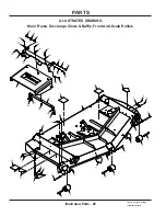
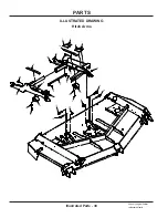
Page 26: ...acement parts ILLUSTRATED DRAWING Main Frame Discharge Chute Baffle Front Anti Scalp Rollers PARTS 12 13 10 11 11 11 11 8 9 9 4 4 4 3 3 3 6 14 5 5 5 7 7 1 1 1 2 2 20 19 18 23 22 22 23 22 23 22 15 16 22 23 18 19 20 18 19 20 17 24 24 24 24 24 21 21 21 23 ...

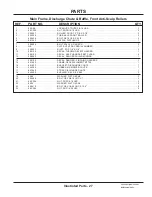
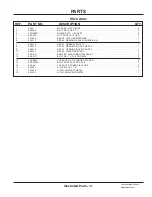
Page 27: ... 10 00 0122 DECAL THROWN OBJECT HAZARD 1 11 00 0123 DECAL KEEP HANDS FEET CLEAR 4 12 00 0062 DECAL DANGER SHIELD MISSING 1 13 00 0102 DECAL DANGER PINCHING HAZARDS 1 14 62 1462 FRAME DECK WELDMENT MT720 1 15 64 1933 BRACKET DISCHARGE CHUTE 1 16 44 0384 RUBBER MS MOWER CHUTE 1 17 64 1942 STRAP DISCHARGE CHUTE 1 18 64 0602 BUSHING 3 8 X 5 8 X 265 3 19 95 06 WASHER FLAT 3 8 SAE 3 20 90 0608 BOLT HEX ...

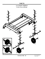
Page 28: ...nly original Ventrac replacement parts 15 14 14 3 3 7 7 4 4 2 2 17 17 8 8 8 8 11 11 11 11 16 10 10 10 10 9 9 9 9 5 5 1 1 1 1 6 6 12 12 12 12 13 13 53 0155 53 0148 37 35 35 36 36 37 35 35 36 36 ILLUSTRATED DRAWING Carrier Frame Wheels ...

Page 29: ... BEARING CUP 4 9 85 B0101 BUSHING 005 SPACER 4 10 85 B0099 BUSHING 875ID X 1 375OD X 120T 4 11 55 LM12749LA2 BEARING TAPER ROLLER CONE 4 12 99 B0119 WASHER MACH 7 8 X 1 3 8 X 10 GA 4 13 99 M0047 LOCKNUT STOVER M22 X 1 5 2 14 05 0172 PLUG RIBBED BLACK LDPE 2 15 00 0383 DECAL VENTRAC 1 16 62 1450 FRAME MAIN CARRIER MS720 1 17 53 0155 WHEEL ASM 13 X 5 X 6 CASTER 2 17 53 0148 WHEEL ASM 13X5X6 RIB FLAT...

Page 30: ...PARTS Illustrated Parts 30 Use only original Ventrac replacement parts 9 6 8 7 10 10 16 16 11 11 3 3 17 18 5 2 2 1 1 15 15 13 13 12 12 4 4 14 14 ILLUSTRATED DRAWING Hitch Arms ...

Page 31: ...ING READ OWNERS MAN 1 7 00 0220 DECAL GENERAL SAFETY 1 8 00 0219 DECAL WARNING DO NOT REACH 1 9 00 0216 DECAL WARNING MOVING PARTS 1 10 00 0427 DECAL WEAR RESISTANT 2 11 05 0169 BUMPER ELASTOMER 1300 LBS PF 2 12 99 K0111 BOLT 5 8 11 X 2 1 4 GRD A325 2 13 99 E0094 LOCKNUT 5 8 11 FLANGED STOVER 2 14 99 SF0506 BOLT SRF 5 16 18 USS X 3 4 2 15 99 A06 LOCKNUT STOVER 3 8 16 USS 2 16 03 0007 PIN BALL 1 2 ...

Page 32: ...PARTS Illustrated Parts 32 Use only original Ventrac replacement parts 1 1 5 5 13 4 11 8 9 7 7 6 6 10 10 10 10 15 14 12 3 2 3 2 2 2 3 3 ILLUSTRATED DRAWING Drive Shaft Attachment Belt ...

Page 33: ...389 SHAFT HITCH ARM 1 5 55 FB16016 1 BEARING FLANGE BLOCK 1 2 6 85 K0410 KEY 1 4 X 1 1 4 2 7 83 H16S BUSHING 1 SPLIT 1 4 KEY 2 8 83 BK45H PULLEY 4 5 H BUSHING 1 9 83 BK55H PULLEY 5 5 H BUSHING 1 10 90 0406 BOLT 1 4 20 USS X 3 4 4 11 81 B045 BELT B45 1 12 99 E0046 NUT U 1 4 20 EXTRUDED 1 13 60 0665 SHIELD DRIVE PULLEY 1 14 95 04 WASHER FLAT 1 4 SAE 1 15 90 0406 BOLT 1 4 20 USS X 3 4 1 Drive Shaft A...

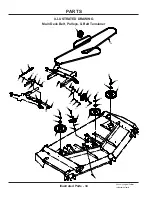
Page 34: ...ts 34 Use only original Ventrac replacement parts ILLUSTRATED DRAWING Main Deck Belt Pulleys Belt Tensioner 19 8 13 18 21 21 21 10 14 22 20 9 9 7 7 7 6 15 15 17 12 12 2 5 1 1 1 1 4 16 16 3 3 3 11 23 24 25 23 24 25 25 24 23 ...

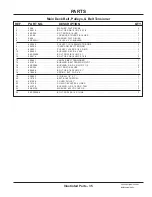
Page 35: ...10 64 0602 BUSHING 3 8 X 5 8 X 265 1 11 99 SF0608 BOLT SRF 3 8 16 UNC X 1 1 12 90 0614 BOLT HEX 3 8 16 UNC X 1 3 4 2 13 40 0401 HANDLE BELT TENSIONER 1 14 64 1936 BUSHING BELT TENSION PIVOT 1 15 85 B0088 BUSHING 5 8 ID X 3 4 OD X 1 2 2 16 99 SF04 NUT SRF 1 4 20 USS 2 17 90 0408 BOLT HEX 1 4 20 UNC X 1 1 18 41 0048 SPRING EXT 1 OD X 6 1 19 03 0022 PIN BALL 1 4 X 1 1 20 81 0162 BELT B180 CUSTOM 1 21...

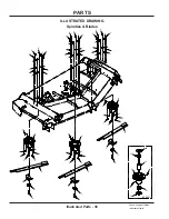
Page 36: ...inal Ventrac replacement parts 5 5 5 4 4 4 6 6 6 9 9 9 2 2 2 2 2 2 2 2 2 2 2 2 2 2 2 2 2 2 8 8 8 1 1 1 1 1 1 1 1 1 1 1 1 1 1 1 1 1 1 7 7 7 3 3 3 3 3 3 3 3 3 3 3 3 3 3 3 3 3 3 87 0241 30 31 27 27 28 29 25 26 ILLUSTRATED DRAWING Spindles Blades ...

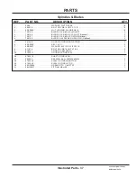
Page 37: ...E 25 X 5 8 RH S GATOR Optional 3 4 79 0106 BLADE 24 15 16X5 8 RH F MULCH Optional 3 5 64 1446 GUARD SPINDLE ANTI STRING 3 6 85 K0408 KEY 1 4 X 1 3 7 99 B0097 WASHER 635 ID X 2 1 2 OD 1 4 3 8 91 1014 BOLT HEX 5 8 18 UNF X 1 3 4 3 9 87 0241 SPINDLE ASM HD RH 3 25 87 0241 1 HOUSING SPINDLE AL 1 26 87 0241 2 SHAFT SPINDLE RH 1 27 55 0095 BEARING BALL 30MM X 62MM 2 28 87 0224 3 SHIELD SPINDLE BOTTOM 1 ...

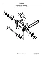
Page 38: ...PARTS Illustrated Parts 38 Use only original Ventrac replacement parts 6 6 1 1 3 3 2 2 4 4 4 4 9 5 5 5 5 8 8 8 8 7 7 7 7 ILLUSTRATED DRAWING Rear Roller ...

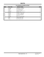
Page 39: ...ASE FTG 1 4 SAE ST 2 2 55 FB16016 2 BEARING 2 BOLT FLANGE 1 2 3 50 0194 ROLLER END 5 DIA X 4 LONG 2 4 64 1930 SPACER REAR ROLLER END 4 5 95 16 WASHER FLAT 1 SAE 4 6 04 0025 SNAP RING EXT 1 SHFT 078 THK 2 7 99 SF0508 BOLT SRF 5 16 18 USS X 1 4 8 99 SF05 NUT SRF 5 16 18 USS 4 9 80 0388 ROLLER REAR MS720 1 Rear Roller ...
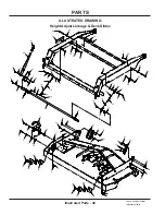
Page 40: ...29 29 2 16 16 19 19 19 19 30 30 20 20 17 18 27 28 1 10 21 21 21 21 21 21 21 21 13 13 13 13 13 13 13 13 6 4 4 24 24 15 15 15 15 22 22 22 22 9 9 3 3 3 3 3 3 3 3 3 3 3 3 3 3 3 11 7 7 7 23 23 23 23 14 14 5 5 5 5 5 5 5 5 5 5 5 5 5 5 5 5 5 5 ILLUSTRATED DRAWING Height Adjust Linkage Deck Slides ...

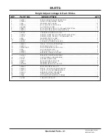
Page 41: ...UNC X 1 1 11 99 A05 LOCKNUT STOVER 5 16 18 USS 1 12 00 0425 DECAL CUT HEIGHT POSITION 1 13 90 0610 BOLT 3 8 16 USS X 1 1 4 8 14 99 J0630NFZ ROD THREADED 3 8 24 X 3 3 4L 2 15 93 06 NUT HEX 3 8 24 UNF 4 16 64 0905 TUBE RD 7 16 X 1 X 1 1 4L 2 17 64 1904 BRACKET FRONT SLIDE LEFT 1 18 64 1905 BRACKET FRONT SLIDE RIGHT 1 19 64 1179 PLATE REAR SLIDE RETAINER 4 20 64 1181 SPACER REAR SLIDE 2 21 90 0606 BO...

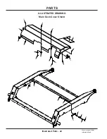
Page 42: ...PARTS Illustrated Parts 42 Use only original Ventrac replacement parts 9 8 7 11 11 10 10 14 18 12 13 4 4 2 2 2 15 15 3 16 16 17 17 1 5 ILLUSTRATED DRAWING Main Deck Cover Shield ...

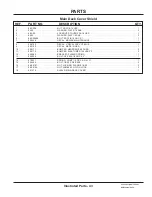
Page 43: ... 00 0428 DECAL MOWER MAINTENANCE 1 8 00 0192 DECAL V DECAL DIE CUT BLUE 1 9 00 0100 DECAL MADE IN USA 1 10 05 0171 BUMPER NEOPRENE 60 DURO 2 11 05 0170 BUMPER ELASTOMER 125 LBS PF 2 12 64 0682 BRACKET SHIELD SPRING 1 13 90 0524 BOLT HEX 5 16 18 UNC X 3 1 14 41 0021 SPRING COMP 1 2 OD X 2 3 4 LG 1 15 99 0406 BOLT 1 4 20 X 3 4 BSCS 2 16 99 E0101 NUT LOCKING FLANGE 1 4 20 2 17 99 E0104 NUT JAM 8 32 N...

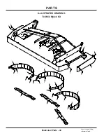
Page 44: ...PARTS Illustrated Parts 44 Use only original Ventrac replacement parts 6 3 4 5 7 7 7 8 8 8 8 8 8 8 2 2 2 2 1 1 1 1 1 1 1 1 1 1 1 ILLUSTRATED DRAWING 70 8164 Mulch Kit ...

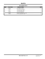
Page 45: ...QTY 1 99 SF05 NUT SRF 5 16 18 USS 11 2 99 0506 BOLT 5 16 18 X 3 4 BSCS 4 3 64 1970 RING MULCHING CENTER 1 4 64 1971 RING MULCHING RIGHT 1 5 64 1982 PLATE DISCHARGE END 1 6 64 1969 RING MULCHING LEFT 1 7 79 0106 BLADE 24 15 16X5 8 RH F MULCH 3 8 97 0506 BOLT CARRIAGE 5 16 X 3 4 7 70 8164 Mulch Kit ...

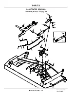
Page 46: ...RTS Illustrated Parts 46 Use only original Ventrac replacement parts 10 9 24 23 8 8 22 20 20 11 1 14 21 5 6 7 4 13 18 17 16 3 3 15 12 2 2 19 23 0168 35 35 ILLUSTRATED DRAWING 70 8163 Hydraulic Flip Up Kit ...

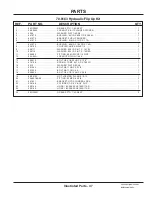
Page 47: ...05 0116 WASHER 544 ID X 817 X 14 RED 1 11 29 0092 FITTING 025 ORIFICE 1 4 PIPE 1 12 99 A04N LOCKNUT NYLON 1 4 20 1 13 90 0412 BOLT HEX 1 4 20 UNC X 1 1 2 1 14 41 0108 SPRING COMP 531 OD X 780 LG 1 15 95 10 WASHER FLAT 5 8 SAE 1 16 90 1044 BOLT 5 8 11 UNC X 5 1 2 1 17 90 1032 BOLT 5 8 11 UNC X 4 1 18 90 0822 BOLT HEX 1 2 13 UNC X 2 3 4 1 19 99 E0103 NUT LOCKING FLANGE 1 2 13 1 20 25 6801 06 06 FITT...

Page 48: ...s or implied including but not limited to a warranty of merchantability or fitness for a particular purpose are made by V P I in connection with the manufacture or sale of its products The engine warranty is covered by its respective engine manufacturer Please refer to the engine manufacturer s war ranty statement that is included in the owner s manual The Ventrac turf equipment including any defe...

Page 49: ...is warranty vii any claims for lost revenue lost profit or additional cost or expense incurred as a result of a claim of breach of war ranty or viii attorney s fees The remedies of buyer set forth herein are exclusive and are in lieu of all other remedies The liability of V P I whether in contract tort under any warranty or otherwise shall not extend beyond its obligation as set forth herein V P I...

Reviews: