SERVICE
Service - 49
Drive Belt Inspection
Always set the parking brake, shut off power
unit engine, remove the ignition key, and ensure
all moving parts have come to a complete stop
before inspecting components or attempting any
repair or adjustment.
Inspecting the belts of this power unit
can prevent
sudden belt failure by finding problems before they
cause the belt to break. Inspect the belts prior to
operation, as part of the daily inspection or anytime
a problem is suspected. There may be a belt prob-
lem if there is a squealing or chattering sound, or
the smell of a slipping belt.
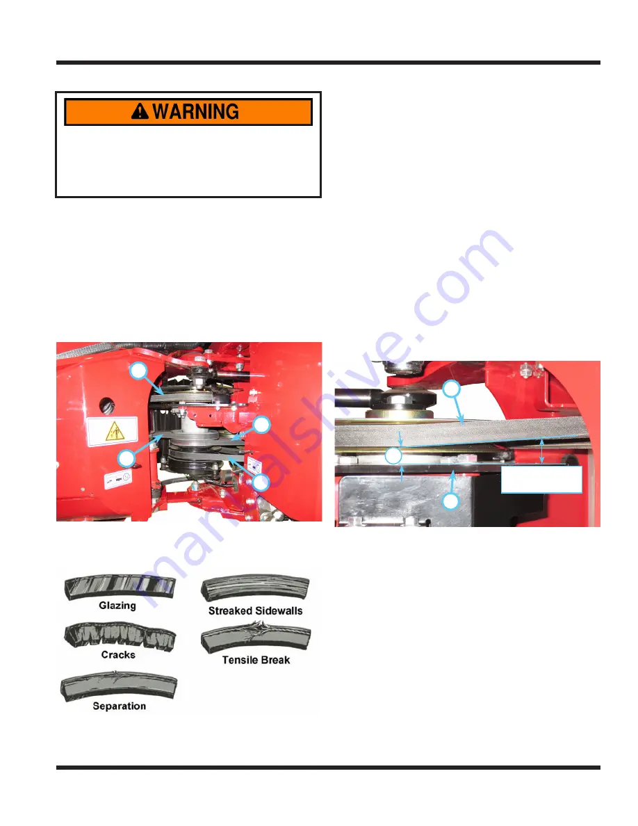
The drive belts that are used on this power unit are
shown below: the engine drive belt (A), the rear
transaxle drive belt (B), the front transaxle drive belt
(C), and the PTO drive belt (D).
A
B
C
D
Typical wear on a drive belt may result in the condi-
tions shown in the diagram. If any of these condi-
tions occur, the drive belt will require replacement.
Engine Drive Belt Inspection & Adjustment
Due to the importance of the engine drive belt being
properly aligned, this belt should be inspected for
proper adjustment every 50 hours.
1. Park the power unit on a level surface.
2.
Engage the parking brake and shut off the engine.
3. Remove the key from the ignition switch and
allow the engine to cool.
4. Remove both center pivot canvas pieces.
5. Remove the top center pivot shield.
6. Make sure the power unit is pointed straight
ahead, not turned to the left or right.
7. At the left side of the center drive pulley, the
engine drive belt (A) should be angled approxi-
mately four degrees up away from the center
spindle mount (B). Measure the vertical distance
between the top of the center spindle mount and
the bottom of the belt, where the belt crosses
the rear edge of the center spindle mount. This
distance should be between .719” (18.3 mm)
and .781” (19.8 mm)
8.
4°
.719” - .781”
(18.3 - 19.8 mm)
A
B
If the measurement is less than .719” (18.3 mm),
the engine frame will need to be moved back-
ward in the rear main frame. If the measurement
is greater than .781” (19.8 mm), the engine
frame will need to be moved forward in the rear
main frame.
9. To adjust the engine frame position, loosen the
4) bolts that fasten the engine frame to the rear
main frame. Note: the left rear engine frame bolt
can be accessed under the rear frame just in
front of the fuel tank with a socket and extension.


