


5
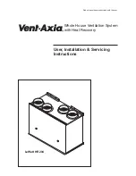
3.0 General Layout
LoWatt HR 204
Exhaust
out to
atmosphere
Fresh air
in from
atmosphere
N
L
1
2
1
2
3
4
5
6
7
8
Normal
Boost
1
2
3
4
5
4
5
6
ON
FRONT
UP
Hot stale air
extracted
in from
wet rooms
Warmed fresh
air supplied
out to
dry rooms
1
2
8
10
9
11
15
6
7
14
4
13
5
12
Fig. 2
3
1.
Heat exchanger
2.
Fan (fresh air in)
3.
Rating label
4.
Fuse
5.
Speed select PCB
6.
Accessory switch connection
7.
Dip switch for speed selection
8.
Lower fixing hole
9.
Alternative outlet for condensate (bottom)
10.
Condensate drain (
Ø
15mm)
11
Condensate tray
12
Alternative outlet for condensate (side)
13
Fan (extraction)
14.
Air filter
15.
Duct connections (4 off)