


11
6.0 Installation Requirements
N
L
1
2
1
2
3
4
5
6
7
8
Normal
Boost
1
2
3
4
5
4
5
6
ON
Remove bottom cover panel
to access the fan speed
settings & condensate connection.
The condensate
outlets
are marked
on the
wall template.
Wall template
Mains
lead
Cable
clamp &
grommet
for
mains
lead
Fuse
Fit fused double
pole isolator
Fit
3 Amp
fuse
Rear exit for
condensate
Cable clips for
accessories lead
FRONT
UP
Knock out
for side exit
condensate
Wall template
HR204 &
HR205
(with cooker hood)
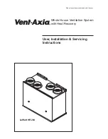
Whole House Ventilation System
Exhaust
Out
Fresh Air
In
Hot Stale
Air In
Warm Air
Out
Minimum
Top
Clearance
200mm
Part No. 372706
98mm
Cooker Hood
Bottom of
MVHR Unit
Bottom of
Cooker Hood
Top of
MVHR
Unit
Bottom of
Mounting
Brackets
4 Fixing Holes
(Key Holes)
Use one
hole each side
Bottom
Fixing Hole
Back Case
Condensate Hole
Side Case Knock
Out Condensate Hole
Minimum Side
Clearance 1mm
Minimum Side
Clearance 1mm
Bottom Condensate
Pipe Exit (HR204 On
ly)
Minimum Bottom Clearance
100mm
(HR204 Model)
Minimum Side
Clearance
24mm
(HR205c)
Minimum Side
Clearance
5mm
(HR204)
MVHR
Side
Minimum Side
Clearance
24mm
(HR205c)
Minimum Side
Clearance
5mm
(HR204)
MVHR
Side
All dimensions
in mm
Minimum Top
Clearance
for servicing
200
Minimum
Side
Clearance
5
Minimum
Side
Clearance
5
Clearances
HR204
Minimum Bottom
Clearance
100
Minimum
Front
Clearance
for
servicing
250
280
Clearances
HR205
Minimum
Side
Clearance
(MVHR)
24
Minimum
Side
Clearance
(MVHR)
24
Minimum
Top Clearance
for servicing
200
300
Minimum
Front
Clearance
for servicing
250
Minimum Bottom
Clearance from Hob
700
Minimum
Side
Clearance
(C.Hood)
1
Measure Minimum
Bottom Clearance
700mm
From Hob
(HR205c Model)
Mains
Cable
Outlet
Top view of unit
Fig. 9
6.4
System controls
6.5
Electrical supply
1. External wiring must be correctly earthed ,
polarised and in accordance with the current
I.E.E. Regulations
.
2. The mains supply must be 220-240V ~ 50Hz
fused at 3 Amps.
6.6
Condensate drain
1. The condensate pipe should have a
continuous fall of 10° (1 in 6) with as much of the
condensate pipe as possible run inside the
property to avoid freezing. The pipe should also
incorporate a trap with a minimum height of
75mm or similar device to prevent a return of
foul air from the waste pipe. See Fig.
.
11
The LoWatt HR204 has three condensate outlet
positions; rear, bottom and left hand side.
Cable
clamp &
grommet
for
accessories
lead
See page 8 for a list of optional controls.
These are used to switch the LoWatt HR204
from normal speed to boost speed.
Note: The method of connection to the
mains supply must facilitate complete
electrical isolation of the appliance.
Connection may be via a fused double pole
isolator with a contact separation of at least
3mm in all poles and supplying the LoWatt
HR204 and its controls only. The LoWatt
HR204 is not designed to be fitted with a
plug.