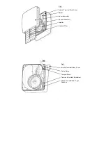
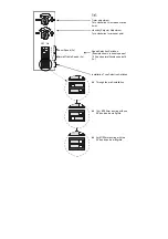


6.
Remove the small Internal Cover that covers the Terminal Block in the top right corner (
fig 3
).
7.
Using the Fan Chassis as a template, carefully sliding the spigot into the Wall Liner, mark the
fixing hole centres on the wall.
8.
Drill and plug the wall using the fixings provided.
9.
Feed the wiring through the hole near the Terminal Block (
fig.
4) and secure the Fan into
position using the screws provided.
10. Select and follow the appropriate wiring diagram in
Section C WIRING.
11. Replace the Internal Cover over the Terminal Block.
12. Ensure the Impeller (
fig.3
) rotates freely.
13. Replace the Front Cover Assembly and tighten the two screws.
14. Switch the mains power supply on and check the fan is operating correctly
FLUSH MOUNTING (PANEL/CEILING)
A Flush Mount Kit (439256) is required.
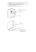
1.
Remove the Front Assembly by slackening 2 Cover Screws by 2 turns (
fig.2).
Lift the front
assembly away from the bottom edge then the top edge.
2.
Mark and cut a rectangular hole 225mm (w) x 255mm (h) through the panel ensuring that
there is sufficient space for the product to be installed and that the optional Filter (
fig.3
) can
be removed for maintenance.
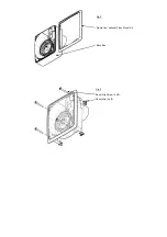
3.
Remove the Back Box by removing the 4 screws. Replace it with the Frame from the
Accessory Kit 439256. (
Fig 5
).
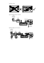
4.
Slide each Panel Clip in to the Chassis then pass each of the long Panel Clip Screws
(supplied in the kit) fully through the flange of the Chassis and screw in to the Panel Clips
(fig.6.)
allowing enough space between the Panel Clip and the flange for the thickness of the
panel (so that the clips can spring open behind the panel).
5.
Set-up the appropriate speed selection and other features as outlined in
Section B SETUP.
6.
Remove the Internal Terminal Block Cover that covers the Terminal Block in the top right
corner (
fig 3 & 4
).
7.
Attach the ducting to the Spigot and locate into the hole in the panel, ensuring the cable is
fed into the Fan Chassis (
fig.
4) and the Panel Clips spring out behind the panel.
8.
Secure into position by carefully tightening the 4 Panel Clip Screws.
IMPORTANT: If power
tools are used, set them to the minimum torque setting or preferably use a manual
screwdriver. Do not over tighten.
9.
Select and follow the appropriate wiring diagram in
Section C WIRING.
10. Replace the Internal Cover over the Terminal Block.
11. Ensure the Impeller rotates freely (
fig.3
).
12. Replace the Front Cover Assembly and tighten the two screws.
13. Switch the mains power supply on and check the fan is operating correctly.
B. SETUP
WARNING: THE FAN AND ANCILLARY CONTROL EQUIPMENT MUST BE
ISOLATED FROM THE POWER SUPPLY DURING INSTALLATION OR
MAINTENANCE.
With the Cover removed the humidity adjustment, overrun timer adjustment, speed selection
switches and installation type switches are accessible in the bottom right corner of the product
(
figs.4 & 7
).
1. SELECTING THE CONSTANT TRICKLE SPEED (0, 6, 9 or 12 l/s)
This will determine the speed at which the fan will run most of the time except when boost is
activated by either the Pullcord, PIR, LS, or Relative Humidity Sensor.
i.
Slide one of the three switches marked as ‘Normal/Trickle Speed’ in
fig.7
to the right (on
position) to select that flow rate for trickle speed.