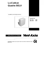
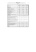
Vent-Axia Lo-Carbon Quadra SELV Series Installation And Wiring Instructions Download Page 11

PRODUCT FICHE 

For Residential Ventilation Units (Complying Commission Delegated Regulation (EU)                 No 

1254/2014) 


Name:


Vent

Axia

Vent

Axia

Vent

Axia

Model


ID


(Stock


Ref.)


:

Lo

Carbon


Quadra


SVTP

 ‐ 

442865

Lo

Carbon


Quadra


SVHTP

 ‐ 

442866

Lo

Carbon


Quadra


SVTM

 ‐ 

442867

SEC


Class

D

D

D

SEC


Value


('Average')

26.23

26.23

26.23

SEC


Value


('Warm')

11.86

11.86

11.86

SEC


Value


('Cold')

51.31

51.31

51.31

Label


Required?


(Yes/No=Out


of


scope)

Yes

Yes

Yes

Declared


as:


RVU


or


NRVU/UVU


or


BVU

RVU

UVU

RVU

UVU

RVU

UVU

Speed


Drive

2

Speed

2

Speed

2

Speed

Type


HRS


(Recuperative,


Regenerative,


None)

None

None

None

Thermal


Eff:


[


(%),


NA(if


none)]

N/A

N/A

N/A

Max.


Flow


Rate


(m3/h)

226.80

226.80

226.80

Max.


Power


Input


(W):


(@Max.Flow


Rate)

38.00

38.00

38.00

LWA:


Sound


Power


Level


(dB)

37.52

37.52

37.52

Ref.


Flow


Rate


(m3/s)

0.04

0.04

0.04

Ref.


Pressure


Diff.


(Pa)

120.00

120.00

120.00

SPI


[W/(m3/h)]

0.24

0.24

0.24

Control


Factor


&


Control


Typology:


(CTRL/


Typology)

Control


Factor;


CTRL

0.65

0.65

0.65

Control


Typology

Clock


Control

Local


Demand


ControlLocal


Demand


Control

Declared:

 ‐

Max


Internal


&


External


Leakage


Rates(%)


for


BVUs


or


carry


over


(for


regenerative


heat


exchangers


only),


&Ext.


Leakage


Rates


(%)


for


Ducted


UVUs;

N/A

N/A

N/A

Mixing


Rate


of


Non

Ducted


BVUs


not


intended


to


be


equipped


with


one


duct


connection


on


either


supply


or


extract


air


side;

N/A

N/A

N/A

Position


and


description


of


visual


filter


warning


for


RVUs


intended


for


use


with


filters,


including


text


pointing


out


the


importance


of


regular


filter


changes


for


performance


and


energy


efficiency


of


the


unit

N/A

N/A

N/A

For


UVUs


(Instructions


Install


Regulated


Supply/Extract


Grilles


Façade)

In


F&W

In


F&W

In


F&W

Internet


Address


(for


Disassembly


Instructions)

www.vent

axia.com www.vent

axia.com www.vent

axia.com

Sensitivity


p.


Var20/

20


Pa:


(for


Non

Ducted


Vus)

N/A

N/A

N/A

Air


Tightness

ID/OD

(m3/h)


(for


Non

Ducted


Vus)

N/A

N/A

N/A

Annual


Electricity


Consumption:


AEC


(kWh/a)

1.97

1.97

1.97

Annual


Heating


Saved:


AHS


(kWh/a)

AHS:


Average

26.23

26.23

26.23

AHS:


Warm

11.86

11.86

11.86

AHS:


Cold

51.31

51.31

51.31


Summary of Contents for Lo-Carbon Quadra SELV Series

Page 1: ...Instructions PLEASE READ INSTRUCTIONS IN CONJUNCTION WITH ILLUSTRATIONS PLEASE SAVE THESE INSTRUCTIONS Lo Carbon Quadra SELV IPX7 Safety Extra Low Voltage Stock Ref N Quadra SVTP 442865 Quadra SVHTP 4...

Page 2: ...hin reach of a person using a fixed bath or shower i e in a nearby wall However the fan must not be placed where it could be submerged in water or regularly exposed to direct water spray e g from a sh...

Page 3: ...installed and that the optional Filter fig 3 could be removed for cleaning The cardboard fitment in the packaging can be used as a template 3 Set up the appropriate speed selection and other features...

Page 4: ...and the flange for the thickness of the panel so that the clips can spring open behind the panel 5 Set up the appropriate speed selection and other features as outlined in Section B SETUP 6 Remove th...

Page 5: ...r RH ii To RAISE the Set Point turn the Humidity Adjuster figs 4 7 CLOCKWISE This makes the fan less sensitive to RH i e the fan will come on at a higher RH C WIRING WARNING THE FAN AND ANCILLARY CONT...

Page 6: ...embly and Impeller in warm soapy water if they are dirty Do not use abrasive cleaners Dry the parts before replacing them 7 Turn the power to the Fan back on The fan has sealed for life bearings which...

Page 7: ...Terminal Block Cover Spigot Cover Assembly Chassis Assembly Impeller Optional Filter Fig 4 Internal Terminal Block Cover Cable Clamp Terminal Block Timer and Humidity Adjustment Speed and Installation...

Page 8: ...Fig 5 Frame from optional Flush Mount Kit Back Box Fig 6 Panel Clip Screw 4 off Panel Clip 4 off...

Page 9: ...e set point Speed Selection Switches Example shown is boost speed of 15 l s and normal trickle speed of 6 l s Installation Type Selection Switches Through the wall installation 1 5m 100mm ducting with...

Page 10: ...Fig 9 Wiring diagram without LS connection Fig 10 Wiring diagram with LS connection N Ls 0V Fan Controller LS L N SELV Supply 24V DC 3A UK 24V LS 24V 0V N Ls 0V Fan Controller LS L N SELV Supply 24V...

Page 11: ...l Factor CTRL 0 65 0 65 0 65 Control Typology Clock Control Local Demand ControlLocal Demand Control Declared Max Internal External Leakage Rates for BVUs or carry over for regenerative heat exchanger...

Page 12: ...e repaired or at the Company s option replaced without charge provided that the product Has been installed and used in accordance with the instructions given with each unit Has not been connected to a...

Reviews: