

Technical Specifications:-
Air Performance: 6, 9, 12, 15, 30 or 60 l/s (22, 32, 43, 54, 108 or 216 m³/h).
Power consumption: 3 - 45W.
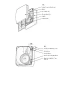
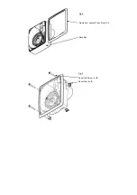
Exhaust spigot diameter: Ø100mm.
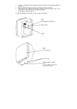
Installed size: 260 x 230 x 112 mm (when surface mounted)
Features:
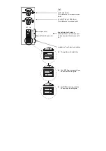
Surface
mountable.
Can be flush mounted with optional accessory kit (439256).
Optional Filter available as an accessory (439927).
Optional Decoration Frame available as an accessory (442551)
Option to boost from constant trickle or from off.
Three trickle speed options available, selectable during installation (6, 9 or 12 l/s).
Three boost speed options available, selectable during installation (15, 30 or 60 l/s).
LS connection (remote switch can switch the fan from the off or trickle state to boost).
Adjustable timer overrun (1-30 minutes approximately).
Model Specific Methods to Select Boost Speed:
SVTP
SVTM
SVHTP
Pullcord
Movement
sensor
(P.I.R)
Adjustable relative humidity sensor
INSTALLATION AND WIRING INSTRUCTIONS
IMPORTANT:
READ THESE INSTRUCTIONS BEFORE COMMENCING THE INSTALLATION
DO NOT install this product in areas where the following may be present or occur:
•
Excessive oil or a grease laden atmosphere.
•
Corrosive or flammable gases, liquids or vapours.
•
Ambient temperatures higher than 40°C or less than –5°C.
•
Possible obstructions which would hinder the access or removal of the Fan.
SAFETY AND GUIDANCE NOTES
A.
All wiring to be in accordance with the current I.E.E. Regulations, or the appropriate standards of your
country and
MUST
be installed by a suitably qualified person.
B.
The electrical supply to this fan is 24v DC SELV from the transformer/controller. This means the fan may be
installed within reach of a person using a fixed bath or shower, i.e. in a nearby wall. However, the fan must
not be placed where it could be submerged in water or regularly exposed to direct water spray, e.g. from a
shower head whether permanently fixed or movable.
C.
ONLY CONNECT TOGETHER THE PRODUCTS FROM THE Lo-CARBON QUADRA SELV RANGE
SINCE THE FANS ARE SPECIALLY DESIGNED TO WORK ON 24v DC AND ARE NOT COMPATIBLE
WITH OTHER VENT-AXIA CONTROLLERS. DO NOT CONNECT MORE THAN ONE FAN TO THE
CONTROLLER.
D.
The controller must not be installed in a shower cubicle or enclosure. It must be away from direct sources of
water spray and out of reach of a person using a fixed bath or shower. Site away from direct sources of
heat.
E.
The controller needs free air circulation and must not be covered with any insulating material such as might
be in a ceiling or roof void.
F.
The Fan should be provided with a local isolator switch capable of disconnecting all poles, having a contact
separation of at least 3mm.
G.
Ensure that the mains supply (Voltage, Frequency, and Phase) complies with the rating label.
H.
The Fan should only be used in conjunction with the appropriate Vent-Axia products.
I.
It is recommended that the connection to the fan connector terminals is made with flexible cable.
J.
When the Fan is used to remove air from a room containing a fuel-burning appliance, ensure that the air
replacement is adequate for both the fan and the fuel-burning appliance.
K.
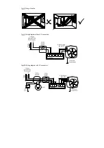
Where ducted Fans are used to handle moisture-laden air, a condensation trap should be fitted. Horizontal
ducts should be arranged to slope slightly downwards away from the Fan.
L.
This appliance is not intended for use by young children or infirm persons without supervision.
M.
Young children should be supervised to ensure that they do not play with the appliance.