Vent-Axia HR100R Installation And Servicing Instructions Download Page 8

3.0 Installation

8

CE-1-11/00

3.1

Installing the Unit

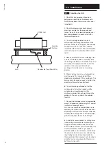
18. External grilles placed in the soffit should

be positioned at the same distances as

indicated for gables.

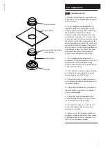
19. The Quicktube Rigid UPVC duct system

permits fast, easy assembly whilst ensuring

pressure-proof system sealing.

20. The ducts are delivered in lengths of 3m

and are easily shortened as required with a

duct saw or a similar fine toothed saw. We

recommend that you file the edges of the ducts

after shortening.

21. Assemble the duct and fittings, following as

closely as possible the diagrammatic ducting

layout. Ensure that the duct is raised above

joist level to allow for thermal insulation of the

ducting.

22. Each straight length of duct is assembled

using a flexible connector (QTC) to join the two

ends, whilst 90° and 45° diversions and

branches are accomplished with flexible fittings

(QTB90, QTB45 and QTET). The duct is a push

fit into the socket of the connector and fittings.

23. Once assembled the joints are secured with

duct tape (DT30) to provide an airtight seal.

Ensure that the tape is secured over the

complete joint area to provide an airtight seal.

24. If the loft space is unheated the unit and

ducting will require to be thermally insulated to

preclude condensation occuring and to

minimise heat loss. This requirement must be

observed in the planning and routing of the

duct system.

25. The insulation recommended is Alreflex 1L1

which comprises 3mm thick polyethylene

bubble sheet laminated on the external surface

with aluminium foil protected by a thin

polythene film. The product is CFC and HFC

free and has a surface spread of flame of Class

1 tested to BS476 Part 7/971. It should,

however, be protected from open flames or

sparks and stored apart from highly flammable

materials.

Summary of Contents for HR100R

Page 1: ...CE 1 11 00 HR100R Mini Air Handling Unit For Ducted Ventilation With Heat Recovery Installation and Servicing Instructions Please leave these instructions with the user...

Page 2: ...CE 1 11 00 2...

Page 3: ...CE 1 11 00 3 1 0 Introduction 4 2 0 Site Requirements 5 3 0 Installation 6 4 0 Electrical 10 5 0 Commissioning 11 6 0 Maintenance 12 7 0 Optional Extras 13 8 0 Notes 14 Section Page Contents...

Page 4: ...involving internal bathrooms and meets building regulation requirements for this application A two speed motor provides for constant low rate ventilation with a boost speed option Fresh pre warmed air...

Page 5: ...ers in the vicinity of excessive levels of airborne oil or grease 7 If the ceiling diffusers are installed in a room containing a fuel burning appliance the installer must ensure that air replacement...

Page 6: ...or blockboard 19mm preferred This board should be raised enough to facilitate the mounting of the unit above joist level 6 The unit must be positioned so that the condensate outlet can be trapped and...

Page 7: ...es it is necessary to lift the floor coverings at first floor level above the terminal positions to gain access to the terminal housings to secure and seal the duct and fittings 12 Fix in position all...

Page 8: ...and 45 diversions and branches are accomplished with flexible fittings QTB90 QTB45 and QTET The duct is a push fit into the socket of the connector and fittings 23 Once assembled the joints are secure...

Page 9: ...se of flexible ducting should be limited to an absolute minimum If used it should be fully stretched in order to minimse pressure loss 29 Offer the unit on to the mounting surface ensuring that it is...

Page 10: ...ow Earth 1 2 1 0 2 Continuous Normal Speed Continuous Boost Speed VCON100 Manual Normal to Boost Speed Switching and ON OFF Control NBSW and PCSW Manual Normal to Boost Speed Control HS6 Automatic Nor...

Page 11: ...two airflows to obtain the overall airflow rates and the individual terminal air flow rates as specified on the air change schedule 3 An airflow meter must be used to set the correct airflows NOTE The...

Page 12: ...on experienced and according to the following procedure 1 Isolate the mains power supply 2 Remove the four securing screws from either end of the cover 3 Remove the cover 4 Remove the heat exchanger f...

Page 13: ...in 6m lengths Ref IFD100 Thermally insulated ducting in 6m lengths Ref PFD100 PVC ducting in 6m lengths Quicktube 100mm rigid plastic ducting can also be used in conjunction with the HR100R unit For...

Page 14: ...8 0 Notes 14 CE 1 11 00...

Page 15: ...CE 1 11 00 15...

Page 16: ...CE 1 11 00 Vent Axia Ltd Fleming Way Crawley West sussex RH10 9YX www vent axia com Comp No 370666 Iss C 0310...

Reviews: