Vent-Axia HR100R Installation And Servicing Instructions Download Page 7

3.0 Installation

7

CE-1-11/00

3.1

Installing the Unit

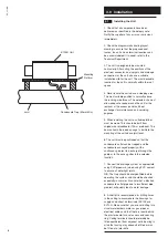
9. Place the terminal housing in the hole in the

ceiling and secure to the back ring with the four

screws provided.

10. For two storey new build properties it is

recommended that the ground floor terminal

housings are secured in position in advance of

the plasterboard panels being fixed, by

obtaining a sheet of plasterboard of the type

and thickness to be used. Cut a square of the

sheet to just span two joists in the corner where

the terminal is to be fitted. Remember that the

edge of the sheet on the inner joist should only

rest on half of the joist thickness. This allows a

fixing surface for the next sheet of plasterboard

to be secured to when it is fitted. Tack up the

plasterboard in position on the ceiling and

connect up and seal the duct and fittings.

11. For two storey existing properties it is

necessary to lift the floor coverings at first floor

level above the terminal positions to gain

access to the terminal housings to secure and

seal the duct and fittings.

12. Fix in position all vertical supply and extract

air ducting being conveyed between ground

floor ceiling level and the loft space.

13. The external grilles for intake and exhaust

air should be positioned so that the exhaust air

is not drawn in again.

14. If the grilles are fitted in the same gable at

the same height, a minimum of 1m between

grilles is recommended.

15. If the grilles are positioned above one

another the distance apart should be at least

1m with the exhaust grille at the top.

16. Roof ventilators placed on the same roof

surface should be positioned at the same

distances as the grilles.

17. Always ensure that all exhaust grilles/roof

ventilators are placed higher than the top edge

of the highest window and at a distance of at

least 1m from the nearest window.
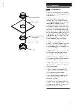
Terminal Housing

Plaster Board

Securing Ring / Back Plate

(for fire valves)

Securing Screw

Terminal

Summary of Contents for HR100R

Page 1: ...CE 1 11 00 HR100R Mini Air Handling Unit For Ducted Ventilation With Heat Recovery Installation and Servicing Instructions Please leave these instructions with the user...

Page 2: ...CE 1 11 00 2...

Page 3: ...CE 1 11 00 3 1 0 Introduction 4 2 0 Site Requirements 5 3 0 Installation 6 4 0 Electrical 10 5 0 Commissioning 11 6 0 Maintenance 12 7 0 Optional Extras 13 8 0 Notes 14 Section Page Contents...

Page 4: ...involving internal bathrooms and meets building regulation requirements for this application A two speed motor provides for constant low rate ventilation with a boost speed option Fresh pre warmed air...

Page 5: ...ers in the vicinity of excessive levels of airborne oil or grease 7 If the ceiling diffusers are installed in a room containing a fuel burning appliance the installer must ensure that air replacement...

Page 6: ...or blockboard 19mm preferred This board should be raised enough to facilitate the mounting of the unit above joist level 6 The unit must be positioned so that the condensate outlet can be trapped and...

Page 7: ...es it is necessary to lift the floor coverings at first floor level above the terminal positions to gain access to the terminal housings to secure and seal the duct and fittings 12 Fix in position all...

Page 8: ...and 45 diversions and branches are accomplished with flexible fittings QTB90 QTB45 and QTET The duct is a push fit into the socket of the connector and fittings 23 Once assembled the joints are secure...

Page 9: ...se of flexible ducting should be limited to an absolute minimum If used it should be fully stretched in order to minimse pressure loss 29 Offer the unit on to the mounting surface ensuring that it is...

Page 10: ...ow Earth 1 2 1 0 2 Continuous Normal Speed Continuous Boost Speed VCON100 Manual Normal to Boost Speed Switching and ON OFF Control NBSW and PCSW Manual Normal to Boost Speed Control HS6 Automatic Nor...

Page 11: ...two airflows to obtain the overall airflow rates and the individual terminal air flow rates as specified on the air change schedule 3 An airflow meter must be used to set the correct airflows NOTE The...

Page 12: ...on experienced and according to the following procedure 1 Isolate the mains power supply 2 Remove the four securing screws from either end of the cover 3 Remove the cover 4 Remove the heat exchanger f...

Page 13: ...in 6m lengths Ref IFD100 Thermally insulated ducting in 6m lengths Ref PFD100 PVC ducting in 6m lengths Quicktube 100mm rigid plastic ducting can also be used in conjunction with the HR100R unit For...

Page 14: ...8 0 Notes 14 CE 1 11 00...

Page 15: ...CE 1 11 00 15...

Page 16: ...CE 1 11 00 Vent Axia Ltd Fleming Way Crawley West sussex RH10 9YX www vent axia com Comp No 370666 Iss C 0310...

Reviews: