


GB
C.
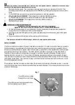
SETUP
WARNING: THE FAN AND ANCILLARY CONTROL EQUIPMENT MUST BE ISOLATED FROM THE
POWER SUPPLY DURING THE INSTALLATION / OR MAINTENANCE.
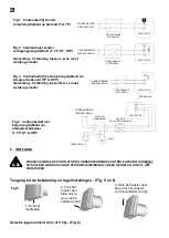
Accessing the wiring and control settings – (Fig. 5 and 6)
Trickle speed selection (6l/s or 9l/s) – (Fig. 6)
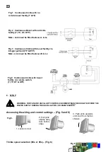
Fig.4 Continuous trickle with boost
facility via remote switch.
(T, TP, HT & HTP)
Fig.1 Continuous trickle with no
remote boost facility (T &TP)
2. Pull grille
slightly away
from bottom
edge.
3. Push grille upwards
until clear from the fan
chassis
.
1. Loosen screw.
Fig.6
Fig.5
.
Fig.2 Continuous Boost with no trickle
facility (T, TP, HT, HTP)
Note:- Link must be fitted between L & Ls
Fig.3 Continuous trickle with boost facility via
integral pullcord (TP & HTP)
Note:- Link must be fitted between N & Ls
Summary of Contents for 8000000009
Page 22: ......
Page 23: ......
Page 24: ...www vent axia be www vent axia nl www vent axia de 473176A 0616...