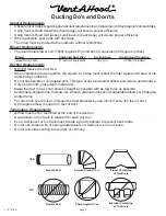
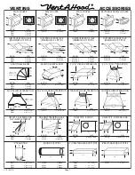
Vent-a-Hood ISLAND RANGE Installation Instructions Manual Download Page 7

Page 7

L111 1015A

VENTING

ACCESSORIES

6” RECTANGULAR DUCT PIPE

MODEL

DIM

VP507

6” x 8 ½”

24”

8 ½”

6”

ROUND DUCT PIPE

MODEL

DIM

VP500

VP501

VP502

6” Round

7” Round

8” Round

36”

6”

7”

8”

3 ¼” RECTANGULAR DUCT PIPE

MODEL

DIM

VP504

VP505

VP506

3 ¼” x 10”

3 ¼” x 12”

3 ¼” x 16”

30”

10”

12”

16”

3 ¼”

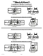
OFFSET L & R TRANSITION

FOR ISLAND BLOWERS

MODEL

DIM

VP542

VP543

Top Left

Top Right

8”

12”

5”

16”

SIDE VENT TRANSITION L & R

FOR ISLAND BLOWERS

MODEL

DIM

VP544

VP545

Left Side

Right Side

19”

8”

16”

5”

OFFSET KIT - RECTANGULAR

MODEL

DIM

VP550

6” Rnd to 3 ¼” x 10”

16”

11”

6”

11”

3 ¼”

10”

STANDARD ISLAND TRANSITION

MODEL

DIM

VP565

5” x 16” to 8”

8”

9”

16”

5”

CLUSTER BLOWER TRANSITION

MODEL

DIM

VP564

8” & 8” to 12”

18 ½”

12”

11 ¼”

“Y” TRANSITION

MODEL

DIM

VP517

VP518

VP551

8” & 8” to 12”

6” & 8” to 12”

6” & 8” to 10”

18”

10”

12”

3 ¼” x 10” BACK VENT ELBOW

MODEL

DIM

VP559

3 ¼” x 10”

4 ¼”

10”

14”

3 ¼”

3 ¼”

MULTI-BLOWER TRANSITION

MODEL

DIM

VP562

VP563

6” & 8” to 10”

8” & 8” to 12”

VP562 - 17 ½”

VP563 - 16 ½”

10”

12”

VP562 - 23 ¼”

VP563 - 30 ½”

3 ¼” x 10” TO 7” TRANSITION

MODEL

DIM

VP521

3 ¼” x 10” to 7”

7”

7 ½”

3 ¼”

10”

LOW PROFILE ROOF JACK

(MAXIMUM 4/12 PITCH)

MODEL

DIM

6 ½”

VP539

VP540

VP541

6” Round

7” Round

8” Round

16 ¾”

16 ¾”

LOW PROFILE ROOF JACK

(MAXIMUM 4/12 PITCH)

MODEL

DIM

10 ½”

VP552

VP553

10” Round

12” Round

22 ½”

20 ¾”

ADJUSTABLE ELBOW

MODEL

DIM

VP513

VP514

VP515

6” Round

7” Round

8” Round

6”

7”

8”

VP513 - 8 ½”

VP514 - 9 9⁄16”

VP515 - 10 5⁄8”

BACK/SIDE VENT ELBOW

MODEL

DIM

VP561

8” to 6” x 8 ½”

12”

6”

16”

8” Round

8 ½”

WALL LOUVER

MODEL

DIM

6”

7”

8”

8 5⁄8”

VP526

VP527

VP528

6” Round

7” Round

8” Round

Back

View

1 ½” Flange

WALL LOUVER

MODEL

DIM

11”

11”

VP554

10” Round

Back

View

1 ½” Flange

WALL LOUVER

MODEL

DIM

13”

13”

VP555

12” Round

Back

View

1 ½” Flange

RECTANGULAR WALL LOUVER

MODEL

DIM

3 ¼”

10”

VP538

VP560

6” x 8 ½“

3 ¼” x 10”

8 ½”

6”

1 ½”

 FLANGE

2” FLANGE

OFFSET KIT - ROUND

MODEL

DIM

VP529

6” Rnd to 7” Rnd

16”

11”

6”

7”

10 ½”

LOW PROFILE ROOF JACK

(MINIMUM 4/12 PITCH)

MODEL

DIM

10 ½”

VP552-HP

VP553-HP

10” Round

12” Round

22 ½”

20 ¾”

M1200 STANDARD TRANSITION

MODEL

DIM

VP566

21” x 8” to 10”

10”

9”

8”

21”

LOW PROFILE ROOF JACK

(MINIMUM 4/12 PITCH)

MODEL

DIM

6 ½”

VP539-HP

VP540-HP

VP541-HP

6” Round

7” Round

8” Round

16 ¾”

16 ¾”

Summary of Contents for ISLAND RANGE

Page 1: ... wall or ceiling do not damage electrical wiring and other hidden utilities C Ducted fans must always be vented to the outdoors D Sufficient air is needed for proper combustion and exhausting of gases through the flue chimney of fuel burning equipment to prevent back drafting Follow the heating equipment manufacturer s guideline and safety standards such as those published by the National Fire Pro...

Page 2: ...ucting Requirements NEVER reduce the duct size When combining ducts together the square inch area must reflect the total square inch area of the ducts being combined Do not use flexible or corrugated duct This type of duct will restrict airflow and reduce performance Only use smooth galvanized metal duct Make the duct run as short and as straight as possible with as few turns as possible Avoid sha...

Page 3: ...s from the base of the duct cover Install the duct cover to the load bearing framework in the ceiling using appropriate hardware through the four inside corner mounting flanges on the top of the duct cover 4 Install the duct s from the outside of the home down to the location of the exhaust outlet s on the top of the transition plus 1 This will allow the transition to engage 1 inside of the duct C...

Page 4: ... 2 Centerline of Hood Electrical 6 Vent Holes 8 Transition Opening 5 x 16 Exhaust Opening Centerline of Hood 18 3 30 9 Installation Details Continued 18 Tall Island Connection Diagram 60 66 Widths 18 Tall Island Connection Diagram 36 54 Widths 550 CFM T200 Dual Blower Top View 1100 CFM T2 200 Dual Blowers Top View 30 Tall Island Connection Diagram 60 66 Widths 30 Tall Island Connection Diagram 36 ...

Page 5: ...al wire clamp through the electrical strap s on the top of the hood deck Install electrical wiring from the service panel to the hood location for each blower assembly Consult the connection diagrams previous page for further details on electrical placement Support the hood under the location where it will hang and feed the electrical wire s through the wire clamp s Tighten the clamp s SKIP STEP 9...

Page 6: ...REMOVABLE BLOWER MOUNTING ASSEMBLY PROCEED DIRECTLY TO STEP 12 While taking care to properly align the duct connection between the transition s and the duct s in the ceiling raise the hood to its final position and attach it to the load bearing framework in the ceiling using appropriate hardware or to the duct cover s using the screws previously removed in Step 3 12 From inside the hood using UL l...

Page 7: ... 23 VP563 30 3 x 10 TO 7 TRANSITION MODEL DIM VP521 3 x 10 to 7 7 7 3 10 LOW PROFILE ROOF JACK MAXIMUM 4 12 PITCH MODEL DIM 6 VP539 VP540 VP541 6 Round 7 Round 8 Round 16 16 LOW PROFILE ROOF JACK MAXIMUM 4 12 PITCH MODEL DIM 10 VP552 VP553 10 Round 12 Round 22 20 ADJUSTABLE ELBOW MODEL DIM VP513 VP514 VP515 6 Round 7 Round 8 Round 6 7 8 VP513 8 VP514 9 9 16 VP515 10 5 8 BACK SIDE VENT ELBOW MODEL ...

Reviews: