


Page 3
L111 1015A
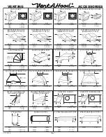
1 ½”
1 ½”
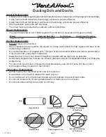
Island Duct Cover
Mounting Holes
(Top View)
5⁄16” Dia.
Installation Details
1) Read all instructions thoroughly before beginning installation. Note: These instructions apply to standard hoods only.
Custom hoods may require additional specification consideration.
2) When installing an island range hood, it is recommended that the bottom edge of the hood be located no more than
30” above the cooking surface for optimum performance.
3) Load-bearing framework in the ceiling is necessary for installation. Additional framework
construction may be required. Do not attach an island hood to a structure that cannot support
twice the weight of the hood.
If applicable, remove the duct cover from its packaging and remove the hood-mounting
screws from the base of the duct cover. Install the duct cover to the load-bearing framework
in the ceiling using appropriate hardware through the four inside corner mounting flanges
on the top of the duct cover.
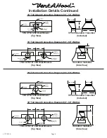
4) Install the duct(s) from the outside of the home down to the location of the exhaust outlet(s) on the top of the transition
plus 1”. This will allow the transition to engage 1” inside of the duct. Consult the connection diagrams (on next page)
for further details on exhaust outlet placement.
Use duct tape to seal all joints. A complete listing of available Vent-A-Hood ducting materials is listed on the back page
of this instruction sheet.
Transition height is as follows:
Island Dual Blower (T200):
8” round duct connects to 9” tall VP565 transition (included).
5) Prepare a protective surface on the floor or countertop for the hood. Remove the hood from its packaging and place
it upside-down on the protective surface for access to the inside of the hood.


