background image

 Part#’s: 0612 & 0616

Page 15

LCD Display

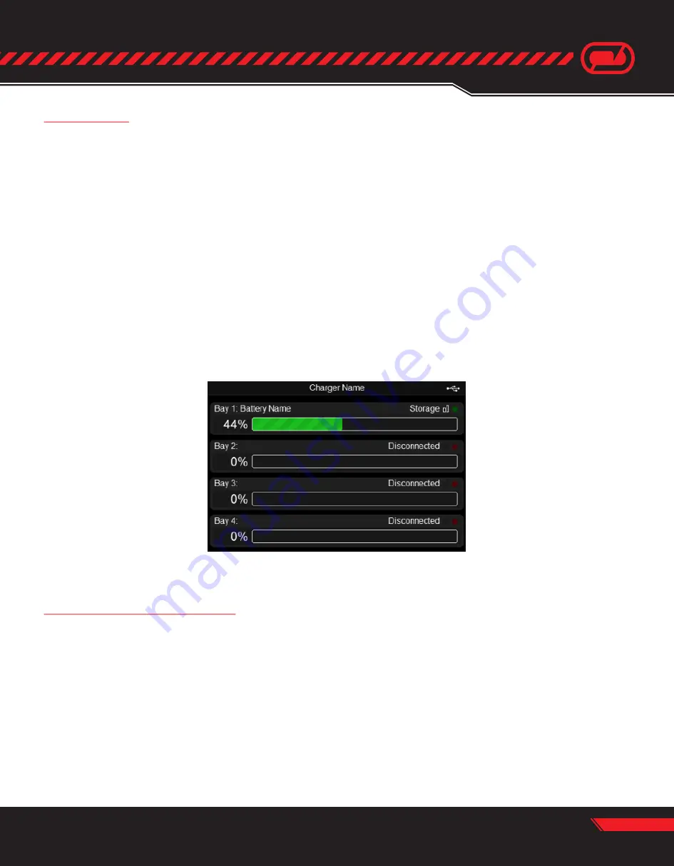
The LCD display shows the status of each bay. Current status is shown in the upper right of each bay segment.
Valid states are:

Battery Bay LED Indicators

Each battery bay has an LED in the lower right corner.

State of charge is shown as a percentage on the left side of each bay segment next to the green bar graph.

• Empty - No battery detected or DJI battery in the bay is off

• Disconnected - No bay inserted

• Connecting - Battery is detected but not configured

• Idle - Battery connected, not charging or discharging
• Charging - Battery is charging
• Storage - Battery is charging or discharging to storage voltage
• Baseline - Battery is undergoing baseline test
• Action Required - Operation paused, see software for further instructions. NOTE - This state 

only shows for teams with supported batteries featuring "On/Off" capabilities

• LED off - Normal operation
• LED flashing red - Indicates a communication fault has occurred, please contact support

• LED flashing green - Indicates the bay containing the selected battery when using the 

“Identify Bay” app feature

LCD Display

Summary of Contents for 0612

Page 1: ...ng LiPo batteries can be hazardous Read this manual in its entirety before attempting to use this product BCMS PRO AND BCMS ULTRA Innovative Safety Features Flexible Scalable to the Needs of Your Oper...

Page 2: ...______________________________________ 9 Chapter III Getting Started Included Required Items________________________________________________________________10 Unpacking________________________________...

Page 3: ...u for purchasing a Venom Commercial Series BCMS Battery Charger Management System This system is the rst of its kind allowing users to easily catalog manage and maintain a eet of batteries from one ea...

Page 4: ...bration 14 Do not disassemble modify or attempt any form of repair of this charger Cautions Warnings Cont System Overview The Venom Commercial Series BCMS Battery Charging Management System allows use...

Page 5: ...USB port for charging mobile devices 6U rack mountable with adjustable rear brackets for added support Proudly designed developed and assembled in the USA Patent pending Simpli ed battery con guration...

Page 6: ...Part s 0612 0616 Page 4 3 88 98 4 8 75 222 3 18 31 465 1 19 00 482 6 29 00 736 6 MAX 24 00 609 6 MIN 10 47 265 9 21 48 545 6 23 84 605 5 4 06 103 2 16 92 429 8 1 75 44 5 Mechanical Drawings...

Page 7: ...Part s 0612 0616 Page 5 Mechanical Drawings Cont 3 83 97 2 5 44 138 1 9 50 241 3 5 9 3 4 0 0 1 8 5 4 4 6 1 1 8 42 213 9 5 6 0 5 6 1 14 00 355 6 11 60 294 6 15 71 399 1...

Page 8: ...2 C19 110V 240VAC Input Front 1 2 3 4 9 10 11 5 6 6 7 8 1 Charge Button 2 Storage Button 3 LCD Display 4 On O Switch 9 Battery Bay Latches 10 Battery Bay LED Indicator 11 Enclosure Mounting Holes 5 U...

Page 9: ...ST XH Balance Connector Port 3 3 JST GH Communicator Port compatible with Venom Commercial Series Batteries 4 4 XT90 Charge Connector Port 5 5 Battery Bay to Charger Chassis Interface Connector Side 1...

Page 10: ...ch utilizes standard 19 spacing width We recommend considering the nal installation weight of a single Venom BCMS to be 100lbs and the selected enclosure must be rated for the appropriate weight handl...

Page 11: ...ior wall The use of any piping other than 4 should be avoided to keep the system in negative pressure as the ventilation system serves only to evacuate smoke generated during a catastrophic battery ev...

Page 12: ...Allen Key Hex Screw x8 Washer x8 Lock Washer x8 240VAC IEC C19 to L6 20P 0616 Only Venom Balance Block w Extended Leads JST XH x4 USB A to USB B cable USB Hub optional Enclosure and mounting hardware...

Page 13: ...ons of this manual DO NOT proceed with installation until the proper power is available at the install location and you have also determined the proper venting as required by your particular circumsta...

Page 14: ...CMS power cord to the appropriate outlet and connecting the USB cable to the computer that will run the Venom BCMS software Please note that multiple systems can be connected to a single computer via...

Page 15: ...and USB driver image 4 6 Complete the steps required for installation of the desktop app and USB driver The USB driver must be installed for the desktop app to communicate properly with the Venom BCMS...

Page 16: ...n gured bays Batteries will be charged or discharged until their con gured target storage voltage is reached The target storage voltage is set in the battery con guration panel of the Venom BCMS softw...

Page 17: ...serted Connecting Battery is detected but not con gured Idle Battery connected not charging or discharging Charging Battery is charging Storage Battery is charging or discharging to storage voltage Ba...

Page 18: ...acks that are used outside of normal operating parameters If you are unsure about how to use or handle any of our products contact Venom for assistance Limitation of Liability VENOM WILL NOT BE SUBJEC...

Page 19: ...comply with the limits for a Class B digital device pursuant to Part 15 of the FCC Rules These limits are designed to provide reasonable protection against harmful interference when the equipment is o...

Page 20: ...ada VENOM POWER 14028 N Ohio Street Rathdrum Idaho 83858 United States of America CUSTOMER SERVICE For quick customer support please visit venompower com or call 800 705 0620 Copyright 2018 Venom Grou...

Reviews: