For the communication with a master device on RS485, the signals
A
and
B
must be routed by a twisted-pair.
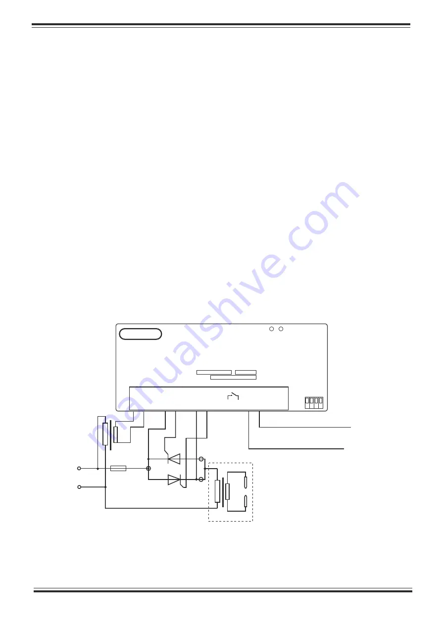
The following diagrams illustrate two-phase connections to a standard dual
thyristor module
:
The connecting wires must be isolated and have minimal cross sectional area
of 0.35-0.75 mm² for
G1
;
K1
and
G2
;
K2
control circuits. The rule to remember for the
2
power wiring is 6А/mm .
The digital input
In
can be driven by PLC outputs, PNP or
NPN logic
.
When
using PNP, the input
In
should be tied to
0V, and the
+24V
input must be connected
to the
PNP output of the PLC
.
On the other hand, when NPN
is used, the
+24V
input
should be tied to the ex24V, and the input
In
must be connected to the NPN
output of the PLC
.
PCN
1
10
Z
P
is designed for DIN mounting in electrical cabinets. The connector
pinout of the controller is pictured on the front panel.
Mechanical installation and wiring
6
2
3
0 V
AC
10 11 12 13 14 15
K2 G2 K1 G1 +24V In
1 2 3 4 5 6 7 8
9
RS485
A B
ID
PCN110ZP
U 2
3
0 / 5 0 H z ; P н = 1 , 8 VA
2 0
2 1
г.
IP20 TC
0 4 П 2 7 0 5 8 - 0 4
N
o
RUN
OUT
VEMA
400VAC
Fuse
~
-
+
Weld transformer
2
3
0
V
A
C
to PLC output
(
NPN
)
or
0V
(
PNP
)
to PLC output
(
PNP
)
or
+24V
(
NPN
)
Fig
.5
Connections diagram for two-phase power supply
Make sure the thyristor module is well ventilated for power rates above
500W!!!


