


F.2 Laser Patterns
Laser firings produced by the sensor can be viewed with an infrared viewer or camera. Photos in this section were taken
with an infrared camera.
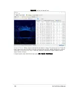
F.2.1 Laser Spot Pattern
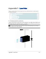
While the terms laser “spot” and “dot” are often used when describing a laser pulse hitting a target, in reality the sensor’s
laser “spot” is a small rectangular area comprised of three smaller bars or bands of light as shown in
Figure F-2 below
.
The long axis of the rectangle coincides with the direction of the laser scan.
The dimensions of this laser spot at the sensor’s ring lens is 9.5 mm tall by 12.7 mm wide - but it doesn’t remain that size as
it speeds away. Read more about that in
Beam Divergence on the facing page
.
Figure F-2 Laser Spot Shape
F.2.2 Laser Scan Pattern
The gap between scan lines can be calculated with the following equation:
Equation F-1 Gap Between Scan Lines
118
VLP-32C User Manual