HDL-64E S3
High Definition LiDAR Sensor
Page 10
Velodyne LiDAR, Inc.
©
2019
63-HDL64ES3 REV K
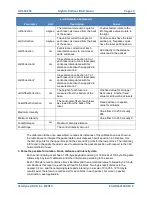
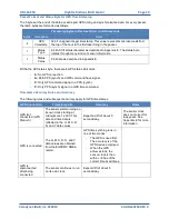
.xml Calibration Parameters
Parameter
Unit
Description
Values
rotCorrection
degree
The rotational correction angle for
each laser, as viewed from the back
of the sensor.
Positive factors rotate to the
left. Negative values rotate to
the right.
vertCorrection
degree
The vertical correction angle for
each laser, as viewed from the back
of the sensor.
Positive values have the laser
pointing up. Negative values
have the laser pointing down.
distCorrection
cm
Far distance correction of each
laser distance due to minor laser
parts’ variances.
Add directly to the distance
value read in the packet.
distCorrectionX
cm
Close distance correction in X of
each laser due to minor laser parts
variances interpolated with far
distance correction then applied to
measurement in X.
distCorrectionY
cm
Close distance correction in Y of
each laser due to minor laser parts
variances interpolated with far
distance correction then applied to
measurement in Y.
vertOffsetCorrection
cm
The height of each laser as
measured from the bottom of the
base.
One fixed value for all upper
block lasers. Another fixed
value for all lower block lasers.
horizOffsetCorrection
cm
The horizontal offset of each laser
as viewed from the back of the
laser.
Fixed positive or negative
value for all lasers.
Maximum Intensity
Value from 0 to 255. Usually
255.
Minimum Intensity
Value from 0 to 255. Usually 0.
Focal Distance
cm
Maximum intensity distance.
Focal Slope
The control intensity amount.
The calibration table, once assembled, contains 64 instances of the calibration values shown in
the table above to interpret the packet data to calculate each point’s position in 3D space. Use
the first 32 points for the upper block and the second 32 points for the lower block. The rotational
info found in the packet header is used to determine the packets position with respect to the 360
o
horizontal field of view.
3. Parse the packets for rotation, block, distance and intensity data.
Each sensor’s data packet has a 1206-byte payload consisting of 12 blocks of 100 byte firing data
followed by 6 bytes of calibration and other information pertaining to the sensor.
Each 100-byte record contains a block identifier and then a rotational value followed by 32 3-byte
combinations that report on each laser fired for the block. Two bytes report distance to the
nearest 0.2 cm, and the remaining byte reports intensity on a scale of 0 to 255. 12 100-byte
records exist, therefore, 6 records exist for each block in each packet. For more on packet
construction, see Appendix E.
Summary of Contents for HDL-64E S3
Page 1: ...USER S MANUAL AND PROGRAMMING GUIDE HDL 64E S3 High Definition LiDAR Sensor ...
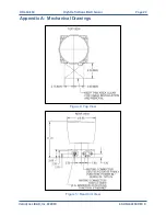
Page 40: ...HDL 64E S3 High Definition LiDAR Sensor Page 40 Velodyne LiDAR Inc 2019 63 HDL64ES3 REV K ...
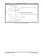
Page 41: ...HDL 64E S3 High Definition LiDAR Sensor Page 41 Velodyne LiDAR Inc 2019 63 HDL64ES3 REV K ...
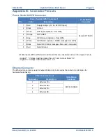
Page 42: ...HDL 64E S3 High Definition LiDAR Sensor Page 42 Velodyne LiDAR Inc 2019 63 HDL64ES3 REV K ...

