background image

VMB4PD 

6

Use 


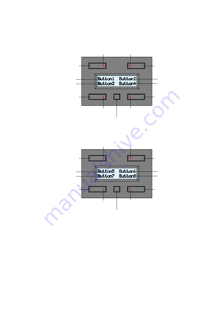
The module consists of 4 push buttons with corresponding LED indication and one configuration push 
button. The label for each push button is displayed on the LCD. 
This module allows defining up to 8 commands. 
The module will display the first 4 commands by default: 


Push the configuration button to switch to the next four commands: 


The module switches back to the default command display after 15 seconds of inactivity. 
You can switch between the two displays at any time by pressing the configuration button.  
 
When pressing, maintaining pressed and releasing a push button, an instruction is being sent on the 
Velbus

®

. These messages identify which push button has been pressed, maintained pressed or released. 

Other modules (relay modules, blind control modules, dimmers...) connected to the Velbus

® 

will react and 

answer by resending a command message to the push button module. This command will switch off, light 
of blink the indication LEDs. 
How a specific push button will control a particular module is explained in the learning mode of the 
concerning modules. 
 

Indication LED command 1

Indication LED command 2 

Indication LED command 3

Indication LED command 4 

Configuration push button

Command 2

Command 4 

Command 1 

Command 3 

Label command 2
Label command 4

Label command 1 
Label command 3 

Indication LED command 5

Indication LED command 6 

Indication LED command 7

Indication LED command 8 

Configuration push button

Command 6

Command 8 

Command 5 

Command 7 

Label command 6
Label command 8

Label command 5 
Label command 7 

Summary of Contents for Velbus VMB4PD

Page 1: ...VMB4PD 1 VMB4PD Push Button and Timer Module for Velbus System...

Page 2: ...range 10m LCD display 2 lines of 16 characters White backlight Adjustable backlight off low dimming high dimming max intensity Possibility to automatically adjust the backlight intensity twice a day A...

Page 3: ...er Area Network Short circuit proof towards negative or positive of power Bus error indication 2 x short flash of the indication LED Self restoring after 25 seconds in case of a bus error Possibility...

Page 4: ...nd the polarity H L BUS 12V VMB4PD L H 12V BUS TWISTED PAIR 0 5mm 2 Connect a 9V battery via the included cable if you desire to power the clock in case of a power failure 12V power supply L H Velbus...

Page 5: ...jumper Remove the jumper in all other cases If different cable wiring topologies tree star loop are used place a jumper on the end module of the longest cable only NOT on each end point Velbus transm...

Page 6: ...utton has been pressed maintained pressed or released Other modules relay modules blind control modules dimmers connected to the Velbus will react and answer by resending a command message to the push...

Page 7: ...ht push button to activate the display menu Press the configuration button to display the next configuration menu Press the upper left push button to activate the mode menu Press the upper right push...

Page 8: ...ule even with a power failure The first configuration menu shows menus Prog and Timer on off when the timer is activated The module will automatically quit the configuration mode after 30 seconds of i...

Page 9: ...guration button pressed for 8 seconds to display the contrast mode The display contrast may be set too low if experiencing a blank display Hold the configuration button pressed for 8 seconds to switch...

Page 10: ...ences This is useful when trying to locate the buttons in a completely dark room 1 Hold the configuration button pressed for 4 seconds to display the configuration menu 2 Press the upper right button...

Page 11: ...imer 9 Enter the first time and intensity using the upper buttons Enter the second time and intensity using the lower buttons In the example above the backlight will be set at full intensity at 08h00...

Page 12: ...he configuration button pressed for 4 seconds to display the configuration menu 2 Press the upper left button to display the clock menu 3 Press the upper right button to set the day 4 Press the lower...

Page 13: ...he display contrast may be set too low if experiencing a blank display Hold the configuration button pressed for 8 seconds to switch the module to the configuration menu which allows modifying contras...

Page 14: ...pressed for 4 seconds to display the configuration menu 2 Press the upper left button to display the clock menu 3 Press the configuration button again to display the next clock menu 4 Press the upper...

Page 15: ...onfiguration menu 3 Press the upper right button to display the address menu 4 Press the upper left button to select the left address digit blinking digit Press the upper right button to select the ri...

Page 16: ...Press the lower right button to display the label editor 4 Move the cursor to the left or to the right using the two upper push buttons Select the character using the two lower push buttons Press the...

Page 17: ...lowing characters can be chosen from 0 P p 1 A Q a q 2 B R b r 3 C S c s 4 D T d t 5 E U e u 6 F V f v 7 G W g w 8 H X h x 9 I Y i y J Z j z K k L l M m N n O _ o Hold a button pressed to scroll Scrol...

Page 18: ...lay the next configuration menu 3 Press the lower left push button to display the reaction time menu 4 Press the lower buttons to set a reaction time of 0 1 2 or 3 seconds for the displayed command Pr...

Page 19: ...reaction time of 0 1 2 or 3 seconds for the displayed command 8 Press the configuration button to quit the reaction time menu Remarks The module will automatically quit the reaction time menu after 3...

Page 20: ...on menu 2 Press the configuration button again to display the configuration menu 3 Press the upper left button to display the mode menu 4 Press the upper right button to set the user mode Following us...

Page 21: ...ation menu 2 Press the lower left button to display the program menu 3 The display shows the first program step program number time and a view of the automated commands Remark The program indications...

Page 22: ...the lower right button to display the previous program step 6 Press the lower left button to modify the displayed program step Next program step Quit program menu Previous program step Quit program m...

Page 23: ...uted every Saturday and Sunday Mo Fr Program step is executed every day except on Saturday and Sunday Mo Sa Program step is executed every day except on Sunday Mo Su Program step is executed every day...

Page 24: ...y on the time day hour minutes programmed and memorized into the program step 11 Press the configuration button to display the next program step setting menu 12 Press the lower buttons to add or to re...

Page 25: ...button to display the next program step setting menu 16 Press the lower buttons to add or to remove the displayed command to or from the program step Label command 5 Label command 6 Add or remove comm...

Page 26: ...1 will be executed every Monday morning at 08h30 commands 3 5 and 8 will be activated briefly Program indications for commands 1 through 4 disappear if the timer function has been activated for the se...

Page 27: ...e command will not be used in the timer program the timer program for a particular command will not be executed the timer program for a particular command is activated The timer indications for comman...

Page 28: ...1 and 2 are not used in the program Go to section 10 if commands 1 through 4 are not used in the program Go to section 12 if commands 1 through 6 are not used in the program 6 Press the lower buttons...

Page 29: ...enter the next timer activation menu The module exits the timer activation menu if commands 5 through 8 are not used in the program go to section 14 Go to section 12 if commands 5 and 6 are not used...

Page 30: ...he module displays the current time and an overview of the active timer programs in this example the timer program for commands 1 3 5 and 8 will be executed Press the configuration button to display t...

Page 31: ...will not be executed the timer program for a particular command is activated Timer indicators for commands 1 through 4 disappear if the timer function is activated for the seconds set of commands onl...

Page 32: ...k will make the module display the corresponding labels Activating commands 5 through 8 on the stick will make the module display the corresponding labels The module will automatically return to the d...

Page 33: ...be set at its maximum Selection of blank characters during labelling Press the configuration button a couple of times until a blinking cursor is displayed in the upper left corner Enter your label usi...

Page 34: ...VMB4PD 34...

Page 35: ...VMB4PD 35...

Reviews: