


_______________________________________________________________________________________________________________________________________________________
6
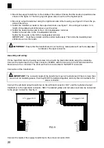
15mm M3 SPACER
8mm SPACER
PCB
VALVE SOCKET
15mm M3 BOLT
Assembly of the main PCB P4040B:
Foreword:
Because of the PCB dimensions, first mount the 8 large tube sockets so that the PCB can rest on a ta-
ble, without the component leads being touched.
When mounting the components, it is best to fold back the component leads a little before turning the
PCB over to solder them.
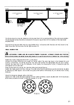
1. VALVE SOCKET MOUNTING
Check the position of the notch in the centre of the tube socket, it must correspond to the notch in the
circle printed on the PCB. Connect the leads to the corresponding isle on the PCB using a small piece of
jumper wire.
IMPORTANT:
Make the connection exactly as shown in the figure, otherwise the small piece of wire could touch the
bottom of the cabinet.
2
3
4
1
3
5
7
4
6
5
8
1
8
q
V1: I.O.
q
V2: I.O.
q
V3: I.O.
q
V4: I.O.
q
V5: I.O.
q
V6: I.O.
q
V7: I.O.
q
V8: I.O.
Also mount a 15 mm spacer on the remaining holes in
the PCB (at the solder side), use a 6 mm M3 bolt:
•
Two spacers round tube sockets V9 and V10
•
A spacer next to RY3
•
A spacer next to T2
•
A spacer next to R1
•
A spacer next to SW1,
together with a lock
washer
at the solder side:
6mm M3 BOLT
M3 LOCK WASHER
15mm M3 SPACER
2
7
1
8
5
4
3
V...
Connect the valve socket terminals 1, 3, 4, 5, and 8 to
the corresponding points at the solder side of the PCB.
Use a piece of jumpwire but take care that the connec-
tion does not come above the spacer, otherwise, the wire
could touch the housing later (see drawing above).


