


Chapter 7 Maintenance and Troubleshooting
JT550 Series Inverter Manua
l
- 88 -
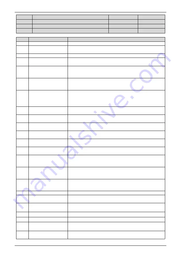
F3.01
Y1 function (open collector output terminal)
Range:0~45
Default:1
F3.02
Y2 function (open collector output terminal)
Range:0~45
Default:0
F3.03
R relay output function selection
Range:0~45
Default:2
F3.04
E relay output function selection
Range:0~45
Default:0
Functions of output terminals:
Value
Function
Description
0
No output
1
inverter running
When the inverter is running and has output frequency(can be zero),
the terminal becomes ON.
2
Fault output (stop)
When the inverter stops due to a fault, the terminal becomes ON.
3
Frequency-level detection
FDT1 output
Refer to the descriptions of F4.19,F4.20.
4
Frequency reached
When the output frequency and set frequency error is less than F4.21
(percentage of the maximum frequency with respect to) the set value,
the output ON.
5
Zero-speed running
(no output at stop)
If the inverter runs with the output frequency of 0, the terminal
becomes ON. If the inverter is in the stop state,the terminal becomes
OFF.
6
Motor overload
pre-warning
The inverter judges whether the motor load exceeds the overload
pre-warning threshold before performing the protection action. If the
pre-warning threshold is exceeded,the terminal becomes ON. For
motor overload parameters,see the descriptions of F9.00~F9.02
。
7
inverter overload
pre-warning
The terminal becomes ON 10s before the inverter overload
protection action is performed.
8
Set count value reached
The terminal becomes ON when the count value reaches the value
set in Fb.08
9
Designated count value
reached
The terminal becomes ON when the count value reaches the value
set in group Fb
10
Length reached
The terminal becomes ON when the detected actual length exceeds
the value set in Fb.05
11
PLC cycle complete
When simple PLC completes one cycle, the terminal outputs a pulse
signal with width of 250 ms.
12
Accumulative running
time reached
If the accumulative running time of the inverter exceeds the time set
in F4.17, the terminal becomes ON
13
Frequency limited
If the set frequency exceeds the frequency upper limit or lower limit
and the output frequency of the inverter reaches the upper limit or
lower limit, the terminal becomes ON.
14
Torque limited
In speed control mode, if the output torque reaches the torque limit,
the inverter enters the stall protection state and meanwhile the
terminal becomes ON.
15
Ready for RUN
If the inverter main circuit and control circuit become stable, and the
inverter detects no fault and is ready for RUN, the terminal becomes
ON.
16
AI1>AI2
When the input of AI1 is larger than tAI2, the terminal ON.
17
Frequency upper limit
reached
If the running frequency reaches the upper limit, the terminal
becomes ON.
18
Frequency lower limit
reached (no output at stop)
If the running frequency reaches the lower limit, the terminal
becomes ON. In the stop state, the terminal becomes OFF.
19
Under voltage state output If the inverter is in undervoltage state, the terminal becomes ON.
20
Communication setting
Refer to the communication protocol.
23
Zero-speed running 2
If the output frequency of the inverter is 0, the terminal becomes ON.
In the state of stop, the signal is still ON.
24
Accumulative power-on
time reached
If the inverter accumulative power-on time (F8.13)exceeds the value
set in F4.16, the terminal becomes ON.


