background image

1

2

3

4

5

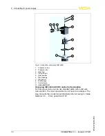
F

ig

.

9

:

C

onnection

,

valve plug

ISO

4400

with

IDC

crimping technology

1

C

ompression nut

2

C

able

3

S

eal ring

4

T

erminal insert

5

P

lug housing

F

or connection to binary inputs of a

PLC

with an input resistance

<

100

k

Ω.

N

ote

:

F

or inputs with an input resistor

>

100

k

Ω,

the instrument signals

failure

.

I

f the input of the

PLC

is high

-

impedance

,

you have to connect a load

resistor

(

R

L

)

with

100

k

Ω

according to the following illustration in

parallel to the input of the

PLC

.

T

ransistor output

VEGASWING

51

• -

transistor

(

PNP

)

17

5

C

onnecting to power supply

30213

-

EN

-

120124

Summary of Contents for VEGASWING 51

Page 1: ...Operating Instructions VEGASWING 51 transistor PNP Document ID 30213 Vibration ...

Page 2: ...n 8 3 4 Storage and transport 9 4 Mounting 4 1 General instructions 10 4 2 Instructions for installation 12 5 Connecting to power supply 5 1 Preparing the connection 14 5 2 Wiring plan 15 6 Set up 6 1 Indication of the switching status 20 6 2 Simulation 20 6 3 Function chart 21 7 Maintenance and fault rectification 7 1 Maintenance 22 7 2 Remove interferences 22 7 3 Exchange of the electronics 23 7 ...

Page 3: ...Editing status 2012 01 10 VEGASWING 51 transistor PNP 3 Contents 30213 EN 120124 ...

Page 4: ...ut into practice by them 1 3 Symbolism used Information tip note This symbol indicates helpful additional information Caution If this warning is ignored faults or malfunctions can result Warning If this warning is ignored injury to persons and or serious damage to the instrument can result Danger If this warning is ignored serious injury to persons and or destruction of the instrument can result E...

Page 5: ...ary conversions or modifications are explicitly forbidden 2 3 Warning about misuse Inappropriate or incorrect use of the instrument can give rise to application specific hazards e g vessel overfill or damage to system components through incorrect mounting or adjustment 2 4 General safety instructions This is a high tech instrument requiring the strict observance of standard regulations and guidelines...

Page 6: ...f www vega com 2 7 Environmental instructions Protection of the environment is one of our most important duties That is why we have introduced an environment management system with the goal of continuously improving company environmental protection The environment management system is certified according to DIN EN ISO 14001 Please help us fulfil this obligation by observing the environmental instruc...

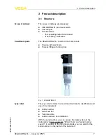
Page 7: ...The type label contains the most important data for identification and use of the instrument l Article number l Serial number l Technical data l Article numbers documentation With the serial number you can access the delivery data of the instrument via www vega com VEGA Tools and serial number search In addition to the type label outside you can also find the serial number on the inside of the instr...

Page 8: ...is detected or in case of power failure the electronics takes on a defined switching condition i e the output is open safe condition The tuning fork is piezoelectrically energised and vibrates at its mechanical resonance frequency of approx 1200 Hz The piezos are fixed mechanically and are hence not subject to temperature shock limitations The frequency changes when the tuning fork is covered by the...

Page 9: ...ompleteness and possible transit damage immediately at receipt Ascertained transit damage or concealed defects must be appropriately dealt with Up to the time of installation the packages must be left closed and stored according to the orientation and storage markings on the outside Unless otherwise indicated the packages must be stored only under the following conditions l Not in the open l Dry a...

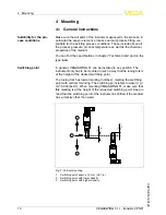
Page 10: ... that the tuning fork is at the height of the desired switching point The tuning fork has lateral marking notches marking the switching point with vertical mounting The switching point refers to water 1 g cm 0 036 lbs in When mounting VEGASWING 51 make sure that this marking is at the height of the requested switching point Keep in mind that the switching point of the instrument is shifted if the ...

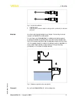
Page 11: ...ion against moisture penetration by leading the connection cable downward in front of the cable entry Rain and condensation water can thus drain off This applies mainly to outdoor mounting as well as installation in areas where high humidity is expected e g through cleaning processes or on cooled or heated vessels Fig 4 Measures against moisture penetration Do not hold VEGASWING 51 on the tuning fo...

Page 12: ...or screwing in 4 2 Instructions for installation For welded socket with O ring in front and welding marking VEGASWING 51 has a defined thread runout This means that every VEGASWING 51 is in the same position after being screwed in Remove therefore the supplied flat seal from the thread of VEGASWING 51 This flat seal is not required when using a welded socket with front flush seal Before welding unscre...

Page 13: ...ducts the surfaces of the tuning fork should protrude into the vessel to avoid buildup Therefore sockets for flanges and mountings bosses should not exceed a certain length 30mm 1 3 16 Fig 6 Adhesive products If VEGASWING 51 is mounted in the filling stream unwanted false measurement signals can be generated For this reason mount VEGASWING 51 at a position in the vessel where no disturbances e g fro...

Page 14: ...on Depending on the plug connection you have to select the outer diameter of the cable respectively so that the seal effect of the cable gland is ensured l Valve plug ISO 4400 ø 4 5 7 mm l Valve plug ISO 4400 with IDC crimping technology ø 5 5 8 mm Use cable with a round wire cross section and tighten the cable gland When mounting outdoors on cooled vessels or in moist areas in which cleaning is ma...

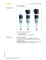
Page 15: ...nnection This plug connection requires a prefabricated cable with plug Depending on the version protection IP 66 IP 67 or IP 68 0 2 bar Valve plug ISO 4400 For this plug version standard cable with round wire cross section can be used Cable diameter 4 5 7 mm protection IP 65 Housing overview Plug versions VEGASWING 51 transistor PNP 15 5 Connecting to power supply 30213 EN 120124 ...

Page 16: ...rol lamp 10 VEGASWING 51 Valve plug ISO 4400 with IDC method of termination For this plug version you can use standard cable with round wire cross section The inner conductors do not have to be stripped The plug connects the conductors automatically when screwing in Cable diameter 5 5 8 mm protection IP 67 16 VEGASWING 51 transistor PNP 5 Connecting to power supply 30213 EN 120124 ...

Page 17: ...of a PLC with an input resistance 100 kΩ Note For inputs with an input resistor 100 kΩ the instrument signals failure If the input of the PLC is high impedance you have to connect a load resistor RL with 100 kΩ according to the following illustration in parallel to the input of the PLC Transistor output VEGASWING 51 transistor PNP 17 5 Connecting to power supply 30213 EN 120124 ...

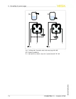
Page 18: ...PA Fig 10 Wiring plan Transistor output with valve plug ISO 4400 PA Potential equalisation RL Load resistor contactor relay etc or external resistor 100 kΩ 18 VEGASWING 51 transistor PNP 5 Connecting to power supply 30213 EN 120124 ...

Page 19: ...Wiring plan housing transistor output with M12 x 1 plug connection 1 Brown 2 White 3 Blue 4 Black RL Load resistor contactor relay etc or external resistor 100 kΩ VEGASWING 51 transistor PNP 19 5 Connecting to power supply 30213 EN 120124 ...

Page 20: ...net changes the current switching condition of the instrument You can check the change on the signal lamp Please note that the connected instruments are activated during the simulation If VEGASWING 51 does not switch over after several tests with the test magnet you have to check the plug connection and the connection cable and try it again If there is no switching function the electronics will be...

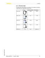
Page 21: ...e switching conditions depending on the adjusted mode and level Level Switching status Control lamp Mode max closed Green Mode max open Red Mode min closed Green Mode min open Red Malfunction any open flashes red VEGASWING 51 transistor PNP 21 6 Set up 30213 EN 120124 ...

Page 22: ...ek round the clock Since we offer this service world wide the support is only available in the English language The service is free of charge only the standard telephone costs will be charged Error Cause Rectification Control lamps off Voltage supply interrupted Check the voltage supply and the cable connection Electronics mo dule defective Exchange the electronics module Signal lamp fla shes red Ther...

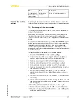
Page 23: ...lows to exchange the electronics module 1 Separate VEGASWING 51 from operating voltage 2 Loosen screw 1 of the valve plug 2 with a wrench loosen M12 x 1 plug connection by turning the compression nut 3 Remove valve plug 2 or M12 x 1 according to drawing 4 Remove lateral fixing screw 7 with a crosstip screwdriver 5 Pull electronics module 4 carefully out of the housing 8 6 Remove the plug of the con...

Page 24: ...NG 51 is again ready for operation 4 1 2 3 5 6 7 8 Fig 17 Exchange of the electronics 1 Fixing screw 2 Valve plug ISO 4400 3 Profile seal 4 Electronics module 5 Rotary switch 16 steps 6 Connection plug 7 Fixing screw 8 Housing 24 VEGASWING 51 transistor PNP 7 Maintenance and fault rectification 30213 EN 120124 ...

Page 25: ...o call back for needed information l Print and fill out one form per instrument l Clean the instrument and pack it damage proof l Attach the completed form and if need be also a safety data sheet outside on the packaging l Please ask the agency serving you for the address of your return shipment You can find the respective agency on our website www vega com under Company VEGA worldwide VEGASWING 51 ...

Page 26: ... to be easily separable WEEE directive 2002 96 EG This instrument is not subject to the WEEE directive 2002 96 EG and the respective national laws Pass the instrument directly on to a specialised recycling company and do not use the municipal collecting points These may be used only for privately used products according to the WEEE directive Correct disposal avoids negative effects on humans and th...

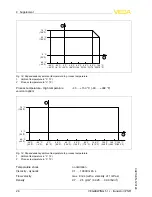
Page 27: ... bolting DN 40 PN 40 bolting DN 50 PN 25 SMS DN 38 PN 6 Max torque process fitting Thread G A NPT 75 Nm 55 lbf ft Thread G1 A 1 NPT 100 Nm 73 lbf ft Surface quality Standard Ra 3 2 µm 1 26 4 in Hygienic version Ra 0 8 µm 3 15 5 in Measuring accuracy Hysteresis approx 2 mm 0 08 in with vertical installation Switching delay approx 500 ms on off Frequency approx 1200 Hz Ambient conditions Ambient tempe...

Page 28: ...150 C 40 302 F 1 2 40 C 40 F 100 C 212 F 120 C 248 F 140 C 284 F 40 C 104 F 60 C 140 F 0 C 32 F 20 C 68 F 150 C 302 F 80 C 176 F 20 C 4 F 0 C 32 F 70 C 158 F 40 C 40 F Fig 19 Dependendency ambient temperature to process temperature 1 Ambient temperature in C F 2 Process temperature in C F Temperature shock no limitation Viscosity dynamic 0 1 10000 mPa s Flow velocity max 6 m s with a viscosity of ...

Page 29: ... consumption max 0 5 W Electromechanical data Valve plug ISO 4400 Wire cross section 1 5 mm 0 06 in Cable outer diameter 4 5 7 mm 0 18 0 28 in Valve plug ISO 4400 with IDC method of termination Wire cross section for wire cross section of 0 5 1 mm 0 02 0 04 in Single wire diameter 0 1 mm 0 004 in Wire diameter 1 6 2 mm 0 06 0 08 in Cable outer diameter 5 5 8 mm 0 22 0 31 in Connection frequency 10...

Page 30: ...epending on the version That s why the associated approval documents have to be noted with these instruments They are part of the delivery or can be downloaded under www vega com via VEGA Tools and serial number search as well as via Downloads and Approvals 30 VEGASWING 51 transistor PNP 9 Supplement 30213 EN 120124 ...

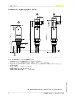
Page 31: ...rd version 1 Thread G A G1 A DIN ISO 228 1 NPT or 1 NPT M12 x 1 1 2 Thread G A G1 A DIN ISO 228 1 NPT or 1 NPT valve plug ISO 4400 3 Thread G A G1 A DIN ISO 228 1 NPT or 1 NPT valve plug ISO 4400 with IDC crimping technology 4 Switching point L Length with G A NPT 66 mm 2 6 in L Length with G1 A 1 NPT 69 mm 2 7 in L Length with switching point L 48 mm 1 9 in 1 Keep in mind that the total length is...

Page 32: ...rature version 1 Thread G A G1 A DIN ISO 228 1 NPT or 1 NPT M12 x 1 2 2 Thread G A G1 A DIN ISO 228 1 NPT or 1 NPT valve plug ISO 4400 3 Thread G A DIN ISO 228 1 NPT or 1 NPT valve plug ISO 4400 with IDC method of termination 4 Switching point L Length with G A NPT 66 mm 2 6 in L Length with G1 A 1 NPT 69 mm 2 7 in L Length with switching point L 48 mm 1 9 in 2 Keep in mind that the total length i...

Page 33: ...4 Fig 22 VEGASWING 51 hygienic versions 1 Clamp valve plug ISO 4400 2 Bolting valve plug ISO 4400 3 SMS 1145 valve plug ISO 4400 4 Switching point L Length with Tri Clamp 53 mm 2 1 in L Length with bolting 53 mm 2 1 in L Length with SMS 1145 53 mm 2 1 in VEGASWING 51 transistor PNP 33 9 Supplement 30213 EN 120124 ...

Page 34: ...ellectuelle Pour plus d informations on pourra se référer au site http www vega com VEGA lineas de productos están protegidas por los derechos en el campo de la propiedad industrial Para mayor información revise la pagina web http www vega com Линии продукции фирмы ВЕГА защищаются по всему миру правами на интеллектуальную собственность Дальнейшую информацию смотрите на сайте http www vega com VEGA...

Page 35: ...VEGASWING 51 transistor PNP 35 9 Supplement 30213 EN 120124 ...

Page 36: ... vega com Printing date ISO 9001 All statements concerning scope of delivery application practical use and operating conditions of the sensors and processing systems correspond to the information avail able at the time of printing VEGA Grieshaber KG Schiltach Germany 2012 Subject to change without prior notice 30213 EN 120124 ...

Reviews: