17
4 Mounting
VEGAPULS WL 61 • Profibus PA
38062-EN-140801
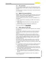
d
h
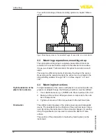
Fig. 13: Deviating socket dimensions
The below charts specify the max. socket piece length h depending
on the diameter d.
Socket diameter d
Socket length h
80 mm
≤ 300 mm
100 mm
≤ 400 mm
150 mm
≤ 500 mm
Socket diameter d
Socket length h
3"
≤ 11.8 in
4"
≤ 15.8 in
6"
≤ 19.7 in
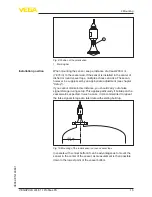
Direct the sensor as perpendicular as possible to the product surface
to achieve optimum measurement results.
Fig. 14: Orientation of the sensor
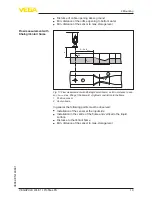
The mounting location of the radar sensor should be a place where no
other equipment or fixtures cross the path of the microwave signals.
Vessel installations, such as e.g. ladders, limit switches, heating spi-
rals, struts, etc., can cause false echoes and impair the useful echo.
Make sure when planning your measuring site that the radar sensor
has a "clear view" to the measured product.
In case of existing vessel installations, a false echo storage should be
carried out during setup.
Sensor orientation
Vessel installations


