background image

connecting the sensors

.

T

his can be conveniently carried out e

.

g

.

in

the workshop

.

Y

ou just need a

24

V

olt power supply as well as an

indicating and adjustment module

PLICSCOM

or the adjustment

software

PACT

ware with

VEGACONNECT

.

M

ove on to electrical connection and proceed as follows

:

1

S

nap the socket without

VEGAMET

625

onto the carrier rail

2

C

onnect sensor cable to terminal

1

/

2

(

active input

)

or

3

/

4

(

passive

input

),

provide a screening

3

W

hen using several sockets

,

loop the power supply by means of

bridges

4

C

onnect power supply

(

switched o

)

to terminal

17

and

18

5

I

f necessary

,

connect relays or other outputs

6

I

nsert

VEGAMET

625

into the plug

-

in socket and screw it down

tightly

N

ote

:

I

f the addressing of the sensors has not yet been carried out

,

only one

sensor must be connected

.

A

ddressing

(

see chapter

"

S

etup

"

)

of the

rst sensor can then be carried out

.

A

fterwards

,

the

rst sensor must

be disconnected again and the next sensor connected and provided
with an address

.

T

hen all sensors can be connected and setup can be

started

.

B

efore setting up

E

x versions

,

make sure the

E

x separating chamber is

plugged on the left housing side

(

above the sensor terminals

).

T

he

pins for type and

E

x coding must also be inserted correctly

.

I

nformation

:

l

O

n the active input

(

terminal

1

/

2

),

VEGAMET

625

provides power

for the connected sensors

.

P

ower supply and measurement data

are transmitted over the same two

-

wire cable

.

T

his mode is

provided for connection of measuring transducers without sepa

-

rate operating voltage

(

sensors in two

-

wire version

).

l

O

n the passive input

(

terminals

3

/

4

),

the sensors are not supplied

with energy

-

only the measured value is transmitted

.

T

his input is

for instruments with their own separate operating voltage

(

sensors

in four

-

wire version or separators such as

VEGATRENN

149

).

O

n

a

VEGAMET

625

in

E

x version

,

the passive input is not available

due to approval

/

technical reasons

.

N

ote

:

VEGAMET

625

is designed for connection of two

HART

sensors

.

B

ecause they are accessed via di

erent addresses in the

HART

multidrop mode

,

both sensors are connected to the same sensor input

.

T

hese are either terminals

1

/

2

(

active input

)

or terminals

3

/

4

(

passive

input

).

S

imultaneous mixed operation on active and passive input is

not possible

.

T

he measured value transmission is carried out via the

VEGAMET

625

D

ouble channel

HART

signal conditioning instrument

13

5

C

onnecting to power supply

28970

-

EN

-

110801

Summary of Contents for VEGAMET 625

Page 1: ...Operating Instructions VEGAMET 625 Double channel HART signal conditioning instrument Document ID 28970 Signal conditioning instruments and communication ...

Page 2: ...ting instructions 10 5 Connecting to power supply 5 1 Preparing the connection 12 5 2 Connection procedure 12 5 3 Wiring plan 14 6 Setup with the integrated indicating and adjustment unit 6 1 Adjustment system 16 6 2 Setup steps 17 6 3 Menu schematic 29 7 Setup with PACTware 7 1 Connecting the PC 37 7 2 Parameter adjustment with PACTware 40 7 3 Setup web server e mail remote enquiry 41 8 Applicati...

Page 3: ...1 Supplement 11 1 Technical data 58 11 2 Overview applications functionality 62 11 3 Dimensions 64 Supplementary documentation Information Supplementary documents appropriate to the ordered version come with the delivery You can find them listed in chapter Product description Editing status 2011 07 06 VEGAMET 625 Double channel HART signal conditioning instrument 3 Contents 28970 EN 110801 ...

Page 4: ...y them 1 3 Symbolism used Information tip note This symbol indicates helpful additional information Caution If this warning is ignored faults or malfunctions can result Warning If this warning is ignored injury to persons and or serious damage to the instrument can result Danger If this warning is ignored serious injury to persons and or destruction of the instrument can result Ex applications Thi...

Page 5: ...ufacturer Arbitrary conversions or modifications are explicitly forbidden 2 3 Warning about misuse Inappropriate or incorrect use of the instrument can give rise to application specific hazards e g vessel overfill or damage to system components through incorrect mounting or adjustment 2 4 General safety instructions This is a high tech instrument requiring the strict observance of standard regulation...

Page 6: ...azardous to water An appropriately certified sensor is the prerequisite for such protection The VEGAMET 625 fulfils the construction and testing principles for overfill protection systems This is certified by the TÜV Technical Control Board statement PP 5003 09 You can download this document from our homepage under Downloads Approvals Signal conditioning instruments Overfill protection 2 9 Environmenta...

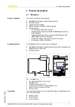
Page 7: ...T 625 signal conditioning instrument with indicating and adjustment unit in the front l Terminal socket VEGAMET 1 2 3 4 9 10 11 12 17 18 20 21 22 5 6 7 8 13 14 15 16 23 24 25 26 27 28 Ser No 12345678 on OK ESC COM 3 2 1 2 3 4 1 6 5 Fig 1 VEGAMET 625 1 Ex separating chamber with Ex version 2 VEGAMET 625 3 Indicating and adjustment unit 4 Communication interface for VEGACONNECT I C 5 RS232 or Ethern...

Page 8: ...d Inventory and remote enquiry The VEGAMET 625 signal conditioning instrument can power two HART sensors and process their measured signals via the same cable The measured value transmission is carried out via a digital bus system HART Multidrop The requested parameter is displayed and also sent to the integrated current outputs for further processing Hence the measured signal can be transferred t...

Page 9: ...ispose of the packaging material via specialised recycling companies Transport must be carried out under consideration of the notes on the transport packaging Nonobservance of these instructions can cause damage to the device The delivery must be checked for completeness and possible transit damage immediately at receipt Ascertained transit damage or concealed defects must be appropriately dealt w...

Page 10: ...ule is not heeded there is a danger of coming into contact with the operating voltage or causing a short circuit A VEGAMET 625 in Ex version is an auxiliary intrinsically safe instrument and may not be installed in explosion endangered areas Before setup the Ex separating chamber must be attached as shown below with Ex versions Safe operation can be only ensured if the operating instructions manua...

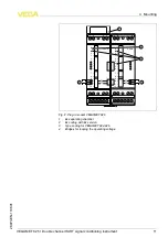
Page 11: ...o 10 o 11 o 12 o N L1 VEGA 1 2 3 4 5 6 7 8 1 4 4 2 3 Fig 2 Plug in socket VEGAMET 625 1 Ex separating chamber 2 Ex coding with Ex version 3 Type coding for VEGAMET 624 625 4 Bridges for looping the operating voltage VEGAMET 625 Double channel HART signal conditioning instrument 11 4 Mounting 28970 EN 110801 ...

Page 12: ... must be made via a ceramic capacitor e g 1 nF 1500 V The low frequency potential equalisation currents are thus suppressed but the protective effect against high frequency interference signals remains Take note of the corresponding installation regulations for Ex applications In particular make sure that no potential equalisation currents flow over the cable screen In case of grounding on both side...

Page 13: ... is plugged on the left housing side above the sensor terminals The pins for type and Ex coding must also be inserted correctly Information l On the active input terminal 1 2 VEGAMET 625 provides power for the connected sensors Power supply and measurement data are transmitted over the same two wire cable This mode is provided for connection of measuring transducers without sepa rate operating vol...

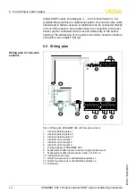
Page 14: ... 13 14 15 16 5 6 7 8 L1 N 1 7 2 3 4 5 6 12 11 13 8 9 10 Fig 3 Wiring plan VEGAMET 625 with two wire sensors 1 Internal operating relay 1 2 Internal operating relay 2 3 Internal operating relay 3 4 Internal current output 1 5 Internal current output 2 6 Internal current output 3 7 Voltage supply of VEGAMET 625 8 Measurement data input with sensor supply active input 9 Measurement data input passive...

Page 15: ...utput 2 6 Internal current output 3 7 Voltage supply of VEGAMET 625 8 Measurement data input with sensor supply active input 9 Measurement data input passive input not in Ex ia 10 Internal fail safe relay 11 HART four wire sensor with Multidrop address 1 12 HART four wire sensor with Multidrop address 2 13 Distributor 14 Power supply for four wire sensors Wiring plan for four wire sensors VEGAMET ...

Page 16: ...g settings for the e mail server For such applications the use of PACTware with appropriate DTMs is recommended Ser No 12345678 on OK ESC COM 3 2 1 3 6 5 7 4 1 2 Fig 5 Indicating and adjustment elements 1 LC display 2 Adjustment keys 3 Communication interface for VEGACONNECT 4 Status indication operation 5 Status indication fail safe relay 6 Status indication interface activity 7 Status indication...

Page 17: ...bserver can be also configured with PACTware Information When using PACTware and the corresponding VEGA DTM additional settings can be carried out which are not possible or only partly possible with the integrated indicating and adjustment unit When using an adjustment software you either need one of the integrated interfaces RS232 Ethernet or the interface converter VEGA CONNECT Further instructio...

Page 18: ... the current measured values will be displayed and outputted As requested the measured value display shows the individual measurement loops separately or in a joint overview The respective digital display value the measurement loop name meas loop TAG and the unit are shown With the separate presentation an analogue bar graph is also displayed and the measured values appear in bigger font size By p...

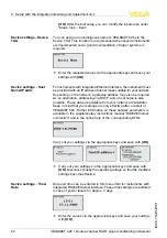
Page 19: ...ed For further information see chapter Application examples à Select the requested application with and save your setting with OK Finally change to the menu item Input with Because VEGAMET 625 has two inputs the measurement loops must be assigned to the inputs After the addresses of the HART sensors are assigned a list of the existing sensors can be prepared and displayed via Sensor selection Sens...

Page 20: ...e only effective after a restart of VEGAMET 625 Further information on these network parameters is available in the supplementary instructions manual RS232 Ethernet connection and in the online help of the corresponding DTMs Carry out your settings via the appropriate keys and save with OK à Carry out your settings via the appropriate keys and save with OK Disconnect briefly the operating voltage so...

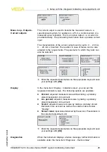
Page 21: ...er The measured variable defines the applicaton of the measurement loop the following settings are available depending on the connected sensor l Level l Process pressure l Temperature l Difference only with measurement loop 3 l Interface l Universal for sensors of other manufacturers The third measurement loop is always a differential measurement loop calculating the difference of the values of measur...

Page 22: ...ntage value e g distance from the sensor to the vessel bottom dry adjustment or adjustment without medium à Save your settings with OK and move to Max adjustment with à As described previously enter now the percentage value for max adjustment and confirm with OK à After entering the percentage value for the max adjustment the suitable distance value must be entered If you want the use the currently...

Page 23: ... should not be displayed in percent but e g in l or kg a scaling can be also set à Enter the requested parameters via the appropriate keys and save your settings with OK Scaling means converting the measured value into a certain parameter and unit The linearized percentage value is the source signal which is used as basis for the scaling The indication can then show the volume in litres e g instea...

Page 24: ...point switch off point Additional modes such as Switching window Flow and Tendency can be only adjusted via PACTware and DTM Select the requested mode and save with OK By pushing you reach the next menu item à Now enter the reference value to which the relay switching points relate By pushing you reach the next menu item à Enter now the switching points for switching the relay on and off The paramet...

Page 25: ...he following options are available l Percent adjusted measured value without taking a probably stored linearization into account l Lin percent adjusted measured value by taking a probably stored linearization into account l Scaled adjusted measured value by taking a probably stored linarization into account as well as the values entered under Scaling l Sensor value input value delivered by the sen...

Page 26: ...e language l Reset on measurement loop The settings of the selected measurement loop will be set to default The measurement loop is deactivated and the TAG name reset to default With every 4 20 mA HART sensor the measured value can be transmitted via analog current signal or digital HART signal This is regulated via the HART mode or the address If a HART sensor is set to address 0 the sensor is in...

Page 27: ...h instrument versions with integrated RS232 Ethernet interface a manual data transmission to a WEB VV server can be trigger for example for test purposes Requirement is that a WEB VV event was configured in advance via PACTware DTM In the menu item Info the following information is available l Sensor type and serial number l Date of manufacture and software version l Date of last change using PC l ...

Page 28: ... Ethernet connection An overview of the standard functions and their adjustment options can be found in chapter Functional overview in the Supplement 28 VEGAMET 625 Double channel HART signal conditioning instrument 6 Setup with the integrated indicating and adjustment unit 28970 EN 110801 ...

Page 29: ...version and application the highlighted menu windows are not always available Measured value indication Device settings VEGAMET 625 Double channel HART signal conditioning instrument 29 6 Setup with the integrated indicating and adjustment unit 28970 EN 110801 ...

Page 30: ...ettings Input Measurement loops 1 2 Input Meas loop 1 2 Change input 30 VEGAMET 625 Double channel HART signal conditioning instrument 6 Setup with the integrated indicating and adjustment unit 28970 EN 110801 ...

Page 31: ...loop 3 Change input Meas loop 1 2 Parameter Meas loop 3 Parameter VEGAMET 625 Double channel HART signal conditioning instrument 31 6 Setup with the integrated indicating and adjustment unit 28970 EN 110801 ...

Page 32: ... loop Adjustment Meas loop Damping Meas loop Linearization curve 32 VEGAMET 625 Double channel HART signal conditioning instrument 6 Setup with the integrated indicating and adjustment unit 28970 EN 110801 ...

Page 33: ...as loop Scaling Meas loop Meas loop TAG Meas loop Output Relay VEGAMET 625 Double channel HART signal conditioning instrument 33 6 Setup with the integrated indicating and adjustment unit 28970 EN 110801 ...

Page 34: ...Meas loop Output Current outputs Display Diagnostics 34 VEGAMET 625 Double channel HART signal conditioning instrument 6 Setup with the integrated indicating and adjustment unit 28970 EN 110801 ...

Page 35: ...Service Service Simulation Service Sensor address VEGAMET 625 Double channel HART signal conditioning instrument 35 6 Setup with the integrated indicating and adjustment unit 28970 EN 110801 ...

Page 36: ...e Data transmission only with option RS232 Ethernet interface Info 36 VEGAMET 625 Double channel HART signal conditioning instrument 6 Setup with the integrated indicating and adjustment unit 28970 EN 110801 ...

Page 37: ...ent of the instrument via PACTware and DTM can be carried out from any PC The measured values can be made available to individual users within the company network as HTML chart As an alternative the independent time or event controlled transmission of measured values via e mail is also possible The measured values can also be called up via a visualisation software Note To contact the instrument a ...

Page 38: ... also possible Remote parameter adjustment of the instrument and the connected sensors is also possible with PACTware 3 2 1 Fig 8 Connection of the modem via RS232 1 Analogue ISDN or GSM modem with RS232 interface 2 RS232 modem connection cable in the scope of delivery 3 RS232 interface RJ45 plug connection Via the RS232 interface direct parameter adjustment and measured value enquiry of the instr...

Page 39: ...on cable in the scope of delivery 4 RS232 interface RJ45 plug connection 5 4 3 2 1 6 8 7 9 1 8 2 1 3 RXD CTS TXD DTR GND RTS 4 2 3 1 5 6 2 8 3 4 5 7 Fig 10 Terminal assignment of the RS232 modem connection cable 1 Name of the interface cable 2 Assignment of the RJ45 plug view contact side 3 Assignment of the RS232 plug view soldering side Assigment RS232 mo dem connection cable VEGAMET 625 Double ...

Page 40: ...rs the addressing must be already carried out see chapter Setup procedure Set HART address If the addressing should be carried out now via PACTware then also only one sensor must be connected When connecting via Ethernet VEGAMET 625 must be provided with a suitable IP address and subnet mask If the project setup is carried out without assistant online mode IP address and subnet mask must be entere...

Page 41: ...ary instructions RS232 Ethernet connection The connection via Modbus TCP or ASCII protocol is described in an additional supplementary instruction Modbus TCP ASCII protocol Both supplementary instructions are attached to each instrument with RS232 or Ethernet interface VEGAMET 625 Double channel HART signal conditioning instrument 41 7 Setup with PACTware 28970 EN 110801 ...

Page 42: ...ed in the signal conditioning instrument During filling relay mode Overfill protection is adjusted The relay is hence switched off safe currentless condition when the max level is exceeded when falling below the min level it is switched on again switch on point switch off point During emptying mode Dry run protection is used This relay is hence switched off when falling below the min level safe current...

Page 43: ...witching status OFF The switching points are adjusted as follows l Relay 1 Switch off point 90 switch on point 85 l Relay 2 Switch off point 5 switch on point 10 Information The switch on and off point of the relays must not be adjusted to the same switching point because this would cause a permanent switchin on and off when this threshold is reached To avoid this effect also with fluctuating product su...

Page 44: ...ttings Application the entry Stand ard and confirm with OK Via the key you reach the next step l Addressing of the sensors Since both sensors are addressed via HART multidrop first of all the sensor addressing must be carried out see chapter Setup procedure Connect sensor 1 for upstream water Enter now under Service Change sensor address in the menu item New address HART address 01 Disconnect sensor...

Page 45: ...s for measurement loop 1 Measurement loop 3 difference The adjustment of the upstream water is taken over automatically 0 0 00m 100 2 m l Relay configuration Select under Measurementloops Meas loop 3 Outputs Relay otuputs Relay 3 Overfill protection Percent the menu item Switching points relay 3 Enter for switching point OFF 10 and for switching point ON 5 With these settings the relay deenergizes at...

Page 46: ...ric value of the upper medium This value is then transferred automatically to VEGAFLEX 67 Further information on the dielectric value are available in the operating instructions manua of VEGAFLEX 67 For this application do not enter a dielectric value directly on VEGAFLEX 67 because this value will be overwritten automatically by VEGAMET 625 l Adjustment Each VEGAFLEX 67 is shipped with default se...

Page 47: ...ure a steady utilization of the pumps is achieved and the reliability increased All relays with activated pump control are not assigned to a certain switching point but are switched on or off depending on the operating time The signal conditioning instrument selects the relay with the shortest operating time when the switch on point is reached and the relay with the longest operating time when the ...

Page 48: ...he previously described example is used as a basis Rel 1 80 On On Off Off On Rel 2 90 On Rel 1 2 10 Off 10 30 20 20 15 t h 5 Rel 1 Rel 2 Fig 14 Example of a pump control 2 Switch on reaction of the pump control 2 When the signal conditioning instrument is switched on the relays are at first in a switched off status Depending on the input signal and the switched on period of the individual relays the...

Page 49: ...which the tendency recognition should respond l Max reaction time Time after which a new measured value generation is carried out and the measured value change is recalculated l Hysteresis is automatically always 10 of the value of Measured value change larger than l Reaction in case of failure In case of a failure the relay goes into the defined condition Note After switching on or a failure alway...

Page 50: ...erates a certain backwater The flow can be determined from the height of this backwater The flow volume is outputted by an appropriate number of pulses on the relay or current output Depending on the type and version each flume generates a different backwater The data of the following flumes are available in the instrument l Palmer Bowlus Flume l Venturi flume trapezoidal weir rectangular weir l Rectang...

Page 51: ...e As the last step select the requested meas unit For above example 0 0 and 100 400 meas unit m h First of all decide if you want to use a relay and or a current output In the DTM window Outputs you can use any of the three outputs as long as these are not yet used for other tasks Finally select under Mode relay or Output characteristics current output the option Flow volume pulse or Sampling puls...

Page 52: ... quantities will continuously enter the flow volume detection despite the empty flume The option Min flow volume suppression offers the possibility to suppress measured flow volumes below a certain percentage value for the flow volume detection 52 VEGAMET 625 Double channel HART signal conditioning instrument 8 Application examples 28970 EN 110801 ...

Page 53: ... The hotline is available to you 7 days a week round the clock Since we offer this service world wide the support is only available in the English language The service is free of charge only the standard telephone costs will be charged The signal conditioning instrument and the connected sensors are permanently monitored during operation and the values entered during parameter adjustment are checke...

Page 54: ...nsor for repair E016 l Empty full adjustment reversed à Carry out a fresh adjustment E017 l Adjustment span too small à Carry out a fresh adjustment and increase the distance between min and max adjustment E021 l Scaling span too small à Carry out a fresh scaling increase the distance between min and max scaling E026 l Units of the input variable are different only differential measurement loop à Ad...

Page 55: ... update is finished à Carry out another software update E053 l Sensor measuring range not read correctly à Communication error Check sensor cable and screening E062 l Pulse priority too small à Increase under Output the entry Pulse output all so that max one pulse per second is outputted E110 l Relay switching points too close together à Increase the difference between the two relay switching points...

Page 56: ...d as follows You can download a return form 23 KB from our Internet homepage www vega com under Downloads Forms and certificates Repair form By doing this you help us carry out the repair quickly and without having to call back for needed information l Print and fill out one form per instrument l Clean the instrument and pack it damage proof l Attach the completed form and if need be also a safety d...

Page 57: ...directive 2002 96 EG and the respective national laws Pass the instrument directly on to a specialised recycling company and do not use the municipal collecting points These may be used only for privately used products according to the WEEE directive Correct disposal avoids negative effects on humans and the environ ment and ensures recycling of useful raw materials Materials see chapter Technical ...

Page 58: ... own power supply Measured value transmission HART multidrop protocol digital for VEGA HART sensors Terminal voltage Non Ex version approx 28 V with 2 sensors 8 mA Ex version approx 18 V with 2 sensors 8 mA Current limitation approx 45 mA 26 mA with Ex Adjustment range HART sensor Adjustment range 10 of sensor measuring range min adjustment delta 0 1 of sensor measuring range Connection cable to t...

Page 59: ...r relating to 20 mA 0 005 K Mode pulse output Voltage pulse 12 V DC at 20 mA with load 600 Ω Pulse length 200 ms Ethernet interface optional Quantity 1 x cannot be combined with RS232 Data transmission 10 100 MBit Plug connection RJ45 Max cable length 100 m 3937 in RS232 interface optional Quantity 1 x cannot be combined with Ethernet Plug connection RJ45 modem connection cable on 9 pole D SUB in ...

Page 60: ...minal socket IP 20 Overvoltage category II Protection class II Electrical separating measures Reliable separation according to VDE 0106 part 1 between power supply input and digital part Reference voltage 250 V Isolation resistance 3 75 kV Galvanic separation between relay output and digital part Reference voltage 250 V Isolation resistance 4 kV Potential separation between Ethernet interface and ...

Page 61: ...th these instruments They are part of the delivery or can be downloaded under www vega com via VEGA Tools and serial number search as well as via Downloads and Approvals VEGAMET 625 Double channel HART signal conditioning instrument 61 11 Supplement 28970 EN 110801 ...

Page 62: ...ue limitation suppression of negative measured values Selection linearisation curve cylindrical tank spherical tank Creation of individual linearisation curves Allocate fail safe relay Modify allocation of outputs Switch on Switch off delay relay Passive input with Ex version Modify HART address of the connected sensors Activate deactivate measurement loop Instrument version with interface option A...

Page 63: ...VEGAMET 625 Double channel HART signal conditioning instrument 63 11 Supplement 28970 EN 110801 ...

Page 64: ... 20 21 22 5 6 7 8 13 14 15 16 23 24 25 26 27 28 Ser No 12345678 72 mm 2 84 130 mm 5 12 87 mm 3 43 110 mm 4 33 119 mm 4 69 55 mm 2 17 on OK ESC COM 64 VEGAMET 625 Double channel HART signal conditioning instrument 11 Supplement 28970 EN 110801 ...

Page 65: ...lus d informations on pourra se référer au site http www vega com VEGA lineas de productos están protegidas por los derechos en el campo de la propiedad industrial Para mayor información revise la pagina web http www vega com Линии продукции фирмы ВЕГА защищаются по всему миру правами на интеллектуальную собственность Дальнейшую информацию смотрите на сайте http www vega com VEGA系列产品在全球享有知识产权保护 进一...

Page 66: ...ctory setting 26 Failure 25 Causes 53 Fault message 25 53 Removal 53 Flow measurement 24 50 Fluctuating product surface 23 Functional principle 8 G Gateway address 20 H HART 12 13 17 26 Horizontal cylindrical tank 42 Host name 20 Hotline 53 HTML 37 Hysteresis 43 I I C interface 37 Input active 13 HART 19 21 Passive 13 Installation 10 Installation possibilities 10 Instrument coding 10 Integration t...

Page 67: ...heet 56 Scaling 23 25 42 Secondary Value 21 Sensor address 26 Sensor input active 13 Passive 13 Sensor search 21 Serial number 8 27 Service 26 Service hotline 53 Simulation 26 Software update 40 Spherical tank 23 Subnet mask 20 Switching window 24 T Tank calculation 40 Tendency 24 Tendency recognition 49 Time setting 20 Type label 7 U USB USB RS232 adapter 38 V Visualization 37 W Web server 41 WEB...

Page 68: ... vega com Printing date ISO 9001 All statements concerning scope of delivery application practical use and operating conditions of the sensors and processing systems correspond to the information avail able at the time of printing VEGA Grieshaber KG Schiltach Germany 2011 Subject to change without prior notice 28970 EN 110801 ...

Reviews: