background image

12

5 Connecting to the sensor

VEGABOX 03 • 

45925-EN-131119

5  Connecting to the sensor

5.1  Preparing the connection

Always keep in mind the following safety instructions:

• 

Connect only in the complete absence of line voltage

• 

If overvoltage surges are expected, overvoltage arresters should 

be installed

The sensor is connected with a fix connected cable to the VEGABOX 

03. The VEGABOX 03 is connected with standard two-wire cable 

without screen to power supply. If electromagnetic interference is 

expected which is above the test values of EN 61326-1 for industrial 

areas, screened cable should be used.
We generally recommend the use of screened cable for HART multi-

drop mode.

In the product configurator of VEGABOX 03, different cable glands 

are available. This selection covers all cable diameters in the range of 

4 … 14 mm (0.157 … 0.551 in).

You can find further information on the cable glands under "

Technical 

data/Electromechanical data

"

If screened cable is necessary, connect the cable screen on both 

ends to ground potential. In the VEGABOX 03, the screen must be 

connected directly to the internal ground terminal. The ground termi-

nal on the outside of the housing must be connected to the potential 

equalisation (low impedance).
If potential equalisation currents are expected, the connection on the 

processing side must be made via a ceramic capacitor (e. g. 1 nF, 

1500 V). The low-frequency potential equalisation currents are thus 

suppressed, but the protective effect against high frequency interfer

-

ence signals remains.

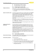
5.2  Connection procedure

The voltage supply and sensor are connected via the spring-loaded 

terminals in the housing of the VEGABOX 03.

Proceed as follows:
1.  Unscrew the housing cover
2.  Loosen compression nut of the cable glands
3.  Remove approx. 7 cm (0.276 in) of the cable mantle, strip approx. 

1 cm (0.4 in) of insulation from the ends of the individual wires

4.  Insert the sensor and the connection cable into VEGABOX 03 

through the cable entry

Safety instructions

Select connection cable

Cable screening and 

grounding

Connection technology

Connection procedure

Summary of Contents for VEGABOX 03

Page 1: ...Operating Instructions Breather housing with ventilation filter VEGABOX 03 Document ID 45925...

Page 2: ...s 9 4 2 Mounting instructions 9 5 Connecting to the sensor 5 1 Preparing the connection 12 5 2 Connection procedure 12 5 3 Wiring plan 14 6 Setup 6 1 Setup steps 17 7 Maintenance and fault rectificati...

Page 3: ...d put into practice by them 1 3 Symbolism used Information tip note This symbol indicates helpful additional information Caution If this warning is ignored faults or malfunctions can result Warning If...

Page 4: ...rning about incorrect use Inappropriate or incorrect use of the instrument can give rise to application specific hazards e g vessel overfill or damage to system components through incorrect mounting o...

Page 5: ...of our homepage 2 6 Environmental instructions Protection of the environment is one of our most important duties That is why we have introduced an environment management system with the goal of contin...

Page 6: ...Tools from the Apple App Store or the Google Play Store Scan the Data Matrix code on the type label of the instrument or Enter the serial number manually in the app The VEGABOX 03 is available with d...

Page 7: ...capacity to handle normal loads during transport is assured by a test based on ISO 4180 The packaging of standard instruments consists of environment friendly recyclable cardboard For special versions...

Page 8: ...osed and stored according to the orientation and storage markings on the outside Unless otherwise indicated the packages must be stored only under the following conditions Not in the open Dry and dust...

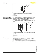
Page 9: ...cable gland Loop the connection cable downward in front of the cable gland This applies particularly to Outdoor mounting Installations in areas where high humidity is expected e g through cleaning pro...

Page 10: ...late is screwed to the socket of VEGABOX 03 by the user 3 2 1 Fig 5 VEGABOX 03 with aluminium and stainless steel housing for carrier rail mounting 1 Base 2 Adapter plate with screws M5 x 12 3 Carrier...

Page 11: ...11 4 Mounting VEGABOX 03 45925 EN 131119 2 1 3 Fig 6 VEGABOX 03 for tube mounting 1 4 screws M5 x 100 2 Mounting brackets 3 Tube diameter 1 to 2...

Page 12: ...creened cable is necessary connect the cable screen on both ends to ground potential In the VEGABOX 03 the screen must be connected directly to the internal ground terminal The ground termi nal on the...

Page 13: ...crewdriver and close the terminals again Information You can find further information on the max wire cross section under Technical data Electromechanical data 8 Check the hold of the wires in the ter...

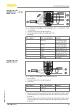
Page 14: ...1 Fig 9 Wiring plan VEGABOX 03 for VEGAWELL 52 4 20 mA 4 20 mA HART 1 To the sensor 2 To power supply or the processing system 3 Shielding1 Wire number Wire colour Polarity Terminal 1 brown 1 2 blue 2...

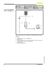
Page 15: ...Red Measurement Pt 100 6 Black Power supply Pt 100 Shielding Grounding 2 3 1 Fig 11 Wiring plan VEGABOX 03 for VEGAPULS WL 61 1 To the sensor 2 To power supply or the processing system 3 Shielding3 Wi...

Page 16: ...TWIST USB LO CK Fig 12 Connection example Connection of a VEGACONNECT to the VEG ABOX 03 1 Sensor 2 Connection cable sensor VEGABOX 03 3 VEGABOX 03 4 Voltage supply signal output sensor depending on t...

Page 17: ...17 6 Setup VEGABOX 03 45925 EN 131119 6 Setup 6 1 Setup steps Setup and adjustment are carried out according to the operating instructions manual of the respective sensor...

Page 18: ...the reason for the fault and the measures taken the steps described in chapter Setup must be carried out again or must be checked for plausibility and completeness 7 3 How to proceed in case of repair...

Page 19: ...We use recyclable materials and have designed the parts to be easily separable Correct disposal avoids negative effects on humans and the environ ment and ensures recycling of useful raw materials Mat...

Page 20: ...be mounting Brackets 316L Mounting screws 316L Weight without mounting element approx Plastic housing 0 35 kg 0 772 lbs Aluminium housing 0 7 kg 1 543 lbs Stainless steel housing 2 0 kg 4 409 lbs Ambi...

Page 21: ...with end sleeve 0 2 1 5 mm AWG 24 16 Supply and signal circuit Operating voltage see operating instructions manual of the respective sensor Electrical protective measures Protection rating Version wi...

Page 22: ...ic housing 79 mm 3 11 69 mm 2 72 74 mm 2 91 82 mm 3 23 97 mm 3 82 6 5 mm 0 26 97 mm 3 82 Fig 13 VEGABOX 03 with plastic housing VEGABOX 03 Aluminium housing 86 mm 3 39 75 2 mm 2 95 79 mm 3 11 82 mm 3...

Page 23: ...using 86 mm 3 39 75 mm 2 95 79 mm 3 11 82 mm 3 23 97 mm 3 82 5 mm 0 2 97 mm 3 82 Fig 15 VEGABOX 03 with stainless steel precision casting housing Mounting elements 82 mm 3 23 97 mm 3 82 7 mm 0 28 11 m...

Page 24: ...lement VEGABOX 03 45925 EN 131119 29 60 mm 1 14 2 36 82 mm 3 23 15 mm 0 59 97 mm 3 82 20 mm 0 79 M6 2 mm 0 08 20 mm 0 79 2 mm 0 08 20 mm 0 79 48 84 mm 1 89 3 31 Fig 17 Brackets for tube mounting of VE...

Page 25: ...tzrechte N here Informationen unter www vega com Les lignes de produits VEGA sont globalement prot g es par des droits de propri t intellec tuelle Pour plus d informations on pourra se r f rer au site...

Page 26: ...26 Notes VEGABOX 03 45925 EN 131119...

Page 27: ...27 Notes VEGABOX 03 45925 EN 131119...

Page 28: ...of delivery application practical use and operat ing conditions of the sensors and processing systems correspond to the information available at the time of printing Subject to change without prior n...

Reviews: