14
5 Connecting to the sensor
VEGABOX 03 •
45925-EN-131119
5.3 Wiring plan
3
2
1
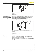
Fig. 8: Terminal compartment VEGABOX 03
1 Spring-loaded terminals for connection of the sensor
2 Release opening
3 Ground terminal for connection of the cable screen
2
3
+
1
-
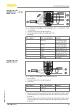
Fig. 9: Wiring plan VEGABOX 03 for VEGAWELL 52 4 … 20 mA, 4 … 20 mA/
HART
1 To the sensor
2 To power supply or the processing system
3 Shielding
1)
Wire number
Wire colour/Polarity
Terminal
1
brown (+)
1
2
blue (-)
2
Shielding
Grounding
Terminal compartment
Wiring plan - VE-
GAWELL 52 4 … 20 mA,
4 … 20 mA/HART
1)
Connect screen to ground terminal. Connect ground terminal on the outside
of the housing to ground as prescribed. The two terminals are galvanically
connected.

