background image


Vega TS-11 / User Manual  


Revision 02 - 27.12.2017 

1 DESCRIPTION AND OPERATION 


Tester sends a special signal to the LoRaWAN™ network (‘Uplink’ packet), in response to 

which the tester received a confirmation (‘Downlink’ packet).   

Tester represents various information about network:  


«Uplink» frequency – frequency on which the request sent to the network (MHz); 


«Downlink»  frequency  -  frequency  on  which  the  confirmation  sent  from  the 
network (MHz); 


SF  (spread  factor)  -  coefficient  determining  the  data  rate  of  «Uplink»  and 
«Downlink» signals; 


Tester’s transmitter power (dBm); 


Requests number; 

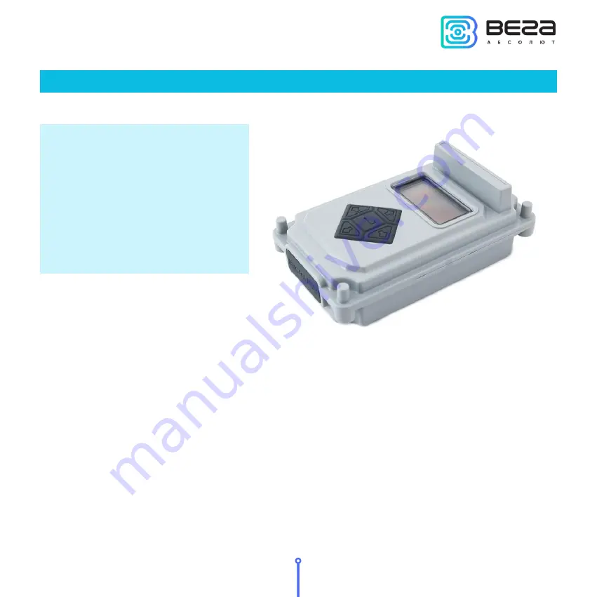
Network tester Vega TS-11 is 

designed for testing LoRaWAN 

networks while them is 

deploying and setting up 

Summary of Contents for TS-11

Page 1: ...VEGA TS 11 User Manual User Manual contains information how to work with LoRaWAN network autonomic tester Vega TS 11 and also contains warranty terms and conditions and rules for operating storage and...

Page 2: ......

Page 3: ...n from Russian Document number V02 TS11 01 Revision and date 02 27 12 2017 This document applies to the following products Product name Type number End devices Vega TS 11 Revision history Revision Dat...

Page 4: ...reen 1 Uplink and Downlink demodulation margin 8 Work screen 2 Full information about the network 12 Work screen 3 Downlink signal RSSI and Uplink demodulation margin diagrams 15 Settings 17 Automatic...

Page 5: ...nts various information about network Uplink frequency frequency on which the request sent to the network MHz Downlink frequency frequency on which the confirmation sent from the network MHz SF spread...

Page 6: ...DM Uplink demodulation margin hereinafter UM DDM Downlink demodulation margin hereinafter DM PER packet error rate relation of the received packets number to the total number of sending packets expres...

Page 7: ...USB 5 V 500 mA LoRaWAN LoRaWAN class Antenna type internal Sensitivity 138 dBm Radio coverage in restrained urban conditions Up to 5 km Radio coverage within line of sight Up to 15 km Transmitter powe...

Page 8: ...ETWORK TESTING Press OK button Press Up button The first pressing connection to the network the second network test Gateways number Uplink demodulation margin in dBm Downlink demodulation margin in dB...

Page 9: ...ndent on what was on the display before button pressing Right and Left buttons is using for navigating through the menu Press OK button for select a menu item Main menu contains the follow items Work...

Page 10: ...itive integer value displayed in dBm and indicating how much received signal above the demodulation threshold 0 value means that the packet was received on the bottom of demodulation 0 dBm whereas for...

Page 11: ...less than 1 and rounding up to integer to 100 the number of confirmations is equal to the number of requests Battery charge displays the current battery charge status When the battery is critically d...

Page 12: ...manual and automatic In the first case the network tester sends an Uplink request to the network each time the Up button is pressed In the automatic mode the tester will send requests itself with the...

Page 13: ...s displayed on the bar located next to the arrow On the arrow is displayed the numerical value of the demodulation margin in dBm of the latest radio communication During the execution of new communica...

Page 14: ...Tester s join status Number of packets transmitted by the tester COUNT UM demodulation margin P power SF spread factor and FQ frequency of the latest transmitted packet Receiving window number of the...

Page 15: ...isplayed as a number of gateways that successfully received the latest packet from the network tester Status line the current transmission status is displayed in text form join TX a request to join th...

Page 16: ...rder COUNT total number of Downlink packets received by the tester DM demodulation margin of the latest transmitted Downlink packet RSSI the latest Downlink packet power expressed as dBm SF Spread fac...

Page 17: ...there is no way to enable disable the automatic network testing mode The left side of the screen displays an RSSI diagram and in the upper left corner the RSSI value for the last received packet in d...

Page 18: ...st received value appears on the left If the communication session was successful and the data was received then the bar on the diagram is filled with white color if the session has not passed or the...

Page 19: ...andard EUR European frequency plan RUS Russian frequency plan Adjust USER plan while pressing the Right Left button an additional screen appears on which you can set a custom frequency plan That scree...

Page 20: ...OFF no logotype and firmware version are displayed there is work screen 1 appears at once Auto off minute set timeout of automatic network tester switch off Timeout sets in minutes from 1 to 60 The t...

Page 21: ...haracteristic sound signal and or the Hourglass icon appear You can disable automatic mode in the same way The first request will be made after the period specified in the settings since the mode was...

Page 22: ...harging starts automatically regardless of whether the device is turned on or off In addition if the device is turned on the charging process is displayed on the screen as an animation of the battery...

Page 23: ...rs Choose Yes and specify the path to the firmware file with the extension vbf 4 Connect the network tester to a personal computer via a USB port and turn on the network tester After the tester is tur...

Page 24: ...n it is necessary to click the Connect button in the Vega LoRaWAN configurator application The firmware file will be downloaded The boot process is displayed both in the configurator and on the networ...

Page 25: ...EQUIREMENTS The network tester Vega TS 11 shall be stored in the original packaging in heated room at temperatures 5 to 40 and relative humidity less than 85 The tester shall be transported in covered...

Page 26: ...Vega TS 11 User Manual 24 Revision 02 27 12 2017 6 CONTENT OF THE PACKAGE Network tester is delivered complete with Network tester Vega TS 11 1 pc Screw 4 pcs Factory certificate 1 pc...

Page 27: ...and operation specified in this user manual Warranty does not apply to power supply elements the device with mechanical electrical and or other damages and defects caused by violation of the transpor...

Page 28: ......

Page 29: ...vega absolute ru User Manual Vega Absolute OOO 2017...

Reviews: