


Q700
12
Programming the Beltpack Operating Mode
(continued)
Programming the
Beltpack Operating
Mode via the QPK-1
Kit and Software.
The QPK-1 consists of an interface unit
and software, and allows programming
the beltpack with the following
advanced functions (in addition to the
basic mode functions described earlier):
1. Default Configuration
2. Pushbutton disable (no action
taken).
3. Pushbutton assignment/
reassignment
("A" = "B", "B" = "A", etc.).
4. Pushbutton duplication
("A" or "B" = "A", ALL = "B", etc.).
The software also allows the user to
assign descriptive names to the
individual beltpacks and graphically set
BP-700 configurations via check boxes.
Connecting the QPK-1
Turn everything on and connect the
QPK-1 interface unit.
1. Connect the serial cable to the
QPK-1 and to Com Port 1 (default)
or Com Port 2 on your computer.
(These instructions assume the
software has been installed on your
computer. If it’s not, see the loading
instructions included with the disk.)
2. Plug the 2.5 mm cable from the
QPK-1 interface into the jack on
the side of the beltpack.
3. Turn on the QPK-1 interface using
the small toggle switch on back.
4. Turn on the BP-700 beltpack to be
programmed (be sure a fresh set of
batteries in installed).
5. Start up the Q700 Application Tools
software on your computer.
If error “Beltpack contains invalid
data” occurs, confirm power to the
beltpack is on units is on and check
all connections. If you connected the
serial cable to Com Port 2, go to
“Com Port” in the menu bar and
select Com Port 2.
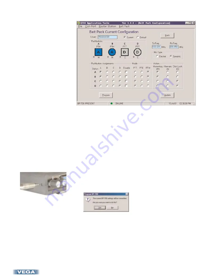
Programming the Operating Mode
• Click “Belt Pack” in the menu bar to
bring up the Belt Pack Configuration
window. This screen indicates the
name of the connected beltpack, the
Tx and Rx frequencies, and a graphic
representation of the mode settings
of the beltpack.
1. For each pushbutton, select the
button assignment (A-D), mode and
action type (the graphic changes to
reflect the settings).
To set the microphone type, select
either “Dynamic” or “Electret.”
2. Click the “program” button to apply
the new settings to the beltpack.
When prompted, enter your
password* and click “Yes” to store
the new settings in the BP-700.
(*see page 9 for default password).
3. Important: In order to apply the
changes, the BP-700 beltpack
power switch MUST be cycled
“off” and then “on” again.
4. To program another beltpack,
connect it to the QPK-1 interface
and repeat steps 1 - 4.
*
Note: It is possible to change the
beltpack Tx and Rx frequencies from
the Belt Pack Configuration Screen. If
doing so, you MUST then connect the
MS-700 master station to coordinate
the frequencies.
Default Configuration
The software allows the user to store a
default configuration in the BP-700.
This feature allows the user to have a
'back-up' (default) Rx/Tx frequency
and/or switch settings that can be
programmed from a standalone beltpack
in the field (without the QPK-1).
• Click the "Default" button in the
Belt Pack Configuration screen (the
default configuration is displayed).
• Modify the frequency and mode
settings of the connected beltpack,
then click the “Program” button
(follow prompts as instructed.)
Note: When a new "Default"
condition is programmed to the
beltpack, the information is stored
into the beltpack EEPROM and can
only be implemented via the
pushbutton programming mode.
Implementing the Default
• Press the "A" and "D" pushbuttons
on the beltpack for more than 7
seconds to enter the programming
mode and then simultaneously
press "C" and "D" for more than 7
seconds to implement the beltpack
defaults. (The "C" and "D" LEDS will
flash alternately for 3 seconds to
indicate implementation of the
defaults, then all four LED's will
triple flash indicating a return to
the top level programming mode.)
• Press "A" and "D" for more than 7
seconds to exit the programming
mode. (See section pages 10 and 11
for more information concerning
the beltpack programming mode).


