background image

7.3 WiFi Wiz

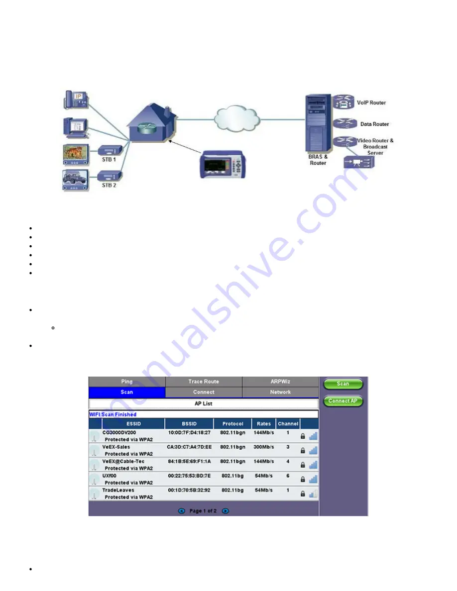
This function allows you to test wireless WiFi 802.11a,b,g,n,ac networks (based on capabilities supported by Wifi USB adaptor

provided by VeEX). A typical application is shown below.

Typical WiFi Wiz Application

The WiFi Wiz function supports:

802.11 a/b/g/n/ac standards (refer to WiFi USB adaptor provided by VeEX)

WEP, WPA, WPA2 Encryption

Scanning

SSID broadcasting and report

Signal Strength

IP Connection and Ping Test

7.3.1 WiFi Procedure

Plug the WiFi adaptor into the USB port. Allow at least 30-45 seconds for the unit to detect the wireless adaptor and for

the software driver to load.

Note:

 Products support USB wireless adaptors supplied by VeEX only and have the necessary software driver built

into the test set.

Tap on the 

Scan

 tab once the test set has detected the wireless USB adaptor.

WiFi Wiz - AP List

AP List

The following information is displayed for each AP:

SSID name of the AP

MTTplus e_Manual D07-00-096P RevA00

Page 43 of 66

Summary of Contents for MTTplus

Page 1: ...MTTplus e_Manual D07 00 096P RevA00 Page 1 of 66...

Page 2: ...Launching Test Applications 4 2 Understanding Test Application GUI 5 0 Utilities 5 1 Platform Settings 5 2 Help 5 3 VeExpress 5 4 R Server Advanced Management 5 5 Software Upgrade 6 0 File Manager 6 1...

Page 3: ...8 0 Warranty and Software 9 0 Certification and Declarations 10 0 About VeEX Go back to TOP MTTplus e_Manual D07 00 096P RevA00 Page 3 of 66...

Page 4: ...n from VeEX Inc This device uses software either developed by VeEX Inc or licensed by VeEX Inc from third parties The software is confidential and proprietary of VeEX Inc The software is protected by...

Page 5: ...y dangerous situation It is recommended to 1 Deactivate the laser before connecting or disconnecting optical cables or patchcords 2 Never look directly into an optical patchcord or an optical interfac...

Page 6: ...also addresses the growing need of fiber test tools for the evolving hybrid FTTx copper networks Telcos can equip their field force with a test toolkit ranging from XDSL technologies as well as for F...

Page 7: ...3 1 MTTplus Overview Side View Go back to TOC MTTplus e_Manual D07 00 096P RevA00 Page 7 of 66...

Page 8: ...een shots Go to Utilities Settings Global Save Settings to set Save Screen and image compression option Volume and Brightness Control it also acts as the MTT F1 key when the is active Brings up the So...

Page 9: ...with the the guides and carefully insert it into place Use the thumb screws to secure it Remove Loosen the thumb screws and carefully pull the module out MTT Modules in MTTplus Carrier Insert Align th...

Page 10: ...ides convenient and immediate access to system features connectivity accessories results etc always at your fingertip Those features are always available independently of whether tests are running or...

Page 11: ...p to two independent tests can run simultaneously Some test applications use the two port groups e g router wrap around test 2 Select the Technology Group 3 Select the desired Test Mode based on the a...

Page 12: ...ions Applications and Tools available for the selected test mode Setup Port and Test Signal configuration D LEDs Test Signal Status E History Clears past events reminder blinking F Current test interf...

Page 13: ...section provides information about the software version serial number and MAC address of the management port of the unit as well as a list of software licenses optional test features currently loaded...

Page 14: ...tion dialog will pop up at the end Use the suggested buttons to accept or discard the new calibration 5 1 3 Bluetooth VeEX products support a micro USB Bluetooth adaptor offering wireless connectivity...

Page 15: ...nnect additional devices Once detected a Bluetooth icon is displayed on screen Devices The test platform will automatically detect the Bluetooth adaptor once plugged into the USB port Details of the B...

Page 16: ...eration you will be prompted to enter a code on the peripheral device PC or Mobile Phone in order to pair successfully Enter the last 4 digits of the V300 serial number as shown in the Connection tab...

Page 17: ...to turn off the backlight if the unit is not in use This function helps improve the battery autonomy and preserve LCD life To enable the timer check Turn off backlight if device is not used for and wi...

Page 18: ...me prefix using the pop up alphanumeric keypad Profile Deleting Auto Delete or Prompt User Profile Saving Auto Overwrite or Prompt User Result Saving Manual or Prompt User Advanced Saving On Off Allow...

Page 19: ...oftware is installed on the PC device The user is able to configure the Profile VNC Server Service Web Service VNC and Web passwords on the Remote Access page Input the test set IP address and specifi...

Page 20: ...convert saved Test Results to PDF Screen Shots View Download PNG format Copy Delete and convert to PDF any screens captured using the UX400 Lock button Remote Control Screen Mirroring It is similar t...

Page 21: ...Web Browser Password Prompt MTTplus e_Manual D07 00 096P RevA00 Page 21 of 66...

Page 22: ...me UTC synchronization to the test set in the form of internal pulse per second 1PPS clock synchronized to the standard second and time stamps This is used to assure that two or more geographically di...

Page 23: ...rational Temperature It is still a major player in the warm up waiting time and it all depends on the ambient temperature and the initial temperature of the test set For example a test set left in the...

Page 24: ...ses no need to connect to the server 5 3 1 Built in VeExpress Client Lets users connect to VeExpress Cloud directly from the test set from the field using any available internet connection e g LAN Wi...

Page 25: ...DC charger to the test set 3 Insert a FAT32 USB Memory Stick into the left side USB port 300MB free 4 Confirm IP connection IP address 5 Check the new software version box 6 Tap on the Download butto...

Page 26: ...2 The install package is in internal memory 3 Turn the test set OFF 6 Power the test set ON 7 The test set software is now up to date Go back to TOC MTTplus e_Manual D07 00 096P RevA00 Page 26 of 66...

Page 27: ...nnection established otherwise a reminder message will pop up Register 1 Enter the IP address of the server A test set must register to an R Server before it can upload results to the server 2 Press t...

Page 28: ...set is authorized you can proceed to Upload Upload To upload result files to the R Server tap the Upload tab and select the desired files Tap on Upload or Upload Del Upload Transfer the selected resu...

Page 29: ...e root of a FAT32 USB memory stick if necessary 2 Insert the memory stick to the USB port located on the left side of the unit 3 Initiate Software Upgrade process Simultaneously press the Alternate Fu...

Page 30: ...he link you received via email or go to www veexinc com using a PC Browser Copy the tar gz install package to the root of a FAT32 USB Memory Insert Memory Stick into a USB port Insert the empty MTT Ca...

Page 31: ...the screen indicating the version discrepancy Press Yes to update the MTT module s firmware This process doesn t require the USB memory stick Note MTT modules updated to work with the new MTTplus may...

Page 32: ...by that specific parameter Tap again to change the sorting order The U L button lock and unlock files to prevent accidental deletion PDF button converts all selected files to PDF format Requires FAT32...

Page 33: ...s Use the stylus to tap on the Y icon Check mark the desired attributes Filters parameters can be combined Reset Filters Press the Show All button Sorting Tap on a header to sort by that field s type...

Page 34: ...folder in the file tree hierarchy The current folder structure is shown in the top bar Open Opens certain file types The USB tool supports one USB memory stick It shows the first memory stick that is...

Page 35: ...if the Data partition is nearly full The Format function is exclusively a maintenance tool Use ONLY when instructed by a VeEX Customer Care representative It erases all the information stored in the t...

Page 36: ...from the DHCP server Gateway and DNS Enable or Disable Enabled If enabled enter the IPv4 address of the Gateway and DNS server in Static mode or use the IP address provided by the DHCP server in DHCP...

Page 37: ...k Gateway PASS indicates that the gateway IP address is valid DNS PASS indicates that the DNS IP address is valid IP Connection Status 7 1 3 Ping The Ping Result provides the number of Sent Received U...

Page 38: ...g and echo response Once the parameters are configured press Start to begin the test Ping Setup Ping Results Pressing Ping will take you to the Result tab and start the Ping test Destination Indicates...

Page 39: ...file or create a new test Destination Enter the IP address or URL of the network device to be detected Time Out Enter the maximum time allowed between an ICMP echo and response at each hop Max Hop Ent...

Page 40: ...Go back to TOC MTTplus e_Manual D07 00 096P RevA00 Page 40 of 66...

Page 41: ...using the numeric keypad Select the test by placing a check mark in the corresponding box of any of the following ARP Ping Net Wiz Setup 7 2 2 Net Wiz Results Summary indicates the test status and re...

Page 42: ...devices Routers Servers Hosts Net Wiz Results Devices Global Detail displays the Attribute MAC and IP Addresses and Ping test results of each device discovered Net Wiz Results Devices Detail Go back t...

Page 43: ...nd report Signal Strength IP Connection and Ping Test 7 3 1 WiFi Procedure Plug the WiFi adaptor into the USB port Allow at least 30 45 seconds for the unit to detect the wireless adaptor and for the...

Page 44: ...side bar Tap on Edit Settings or Connect AP to change the Encryption Type and enter the WiFi Key Encryption Type Supported encryption types include WEP WPA and WPA2 Key Security phrase or password ne...

Page 45: ...annel connected to Encryption Encryption type Mode Signal Radio signal level dBm Link quality score Max data rate 802 11 protocols supported WiFi Wiz Connection Status After a successful connection to...

Page 46: ...Go back to TOC MTTplus e_Manual D07 00 096P RevA00 Page 46 of 66...

Page 47: ...he core or damage to the cladding close to the core are unacceptable Slight scratches and small pits on the cladding away from the core are however acceptable Cracks are not permitted in neither core...

Page 48: ...lly freezes the picture captures the image and runs the IEC 61300 3 35 analysis No need to move hands or press any buttons movement and vibration are common causes of focus loss No PC required for ima...

Page 49: ...taps on the Analysis OFF button the analysis function is turned OFF and the button toggles to show Analysis ON These soft buttons should be interpreted as Go to Freeze Allows users to manually freeze...

Page 50: ...end face images that have been captured with the fiber inspection microscope Users can and Before and After identifiers or remainders when comparing images before or after cleaning or polishing Clear...

Page 51: ...to navigate select and load any other file Show Hide Overlay Enables or disables the mask anomalies identification and analysis Finer From To User customizable labels to identify the fiber under test...

Page 52: ...e defects and scratches count by sizes and position used for the evaluation of the Pass Fail criteria according to the IEC 61300 3 35 standard 7 4 2 Optical Power Meter OPM MTTplus e_Manual D07 00 096...

Page 53: ...You must connect the LS to the OPM dongle using a short patch cord and tap on the Reference button to record the 0dB point Then that LS can be connected to the far end of the fiber to measure the los...

Page 54: ...devices etc It offers the following capabilities Helps determine the best available WLAN channels quickly for optimal performance Helps to visualize and locate RF signals in the 2 4GHz and 5GHz spect...

Page 55: ...t across the entire spectrum Spectral view Historical view of wireless spectrum use at a point in time WiFi SA Planar View Planar View Traditional Spectrum Analyzer view with Max Average and Current r...

Page 56: ...indication of the typical local network conditions WiFi SA Spectral View Spectral View Waterfall type view across the whole band graphs amplitude levels over time Uses color to pick out the relative s...

Page 57: ...sidebar and click the pattern in the Topographic view to identify a device WiFi SA Inspector Inspector The Inspector button setup allows the user to measure the frequency of the RF activity or interf...

Page 58: ...the user to select frequency band for testing 7 4 4 Data Card To establish an IP connection using a data card please make sure that the data card is connected on the USB port Note that only datacards...

Page 59: ...ration parameters then press Connect Now that a connection has been established The D for Data in the icon turns green The connection details are displayed in the IP Tools Status tab shown below It wi...

Page 60: ...s AP detected in the 2 4 GHz and 5GHz bands The following information is displayed for each AP SSID name of the AP BSSID MAC address of the AP 802 11 protocol version supported by the AP Max data rate...

Page 61: ...vigate the graph and get additional information for the access points Detailed information for each Access Point includes SSID name of the AP AP s radio Channel number Signal strength dBm Number of co...

Page 62: ...S OTDR RXT 4100 OTDR FX300 OTDR or SunLite OTDR test sets It can also be used to control the wireless OPX BOX OTDR via Bluetooth or USB connection offering full featured OTDR functionality Please refe...

Page 63: ...ity The built in web browser uses the management port IP connection An active IP connection can be established either through Ethernet WiFi or datacard ports The web browser defaults to VeEX s website...

Page 64: ...by the customer along with proof of purchase within thirty 30 days of the request by the customer freight prepaid Additionally during the warranty period VeEX Inc will provide without charge to the cu...

Page 65: ...and European Free Trade Association EFTA EN61010 1 For a copy of the CE Declaration of Conformity relating to VeEX products please contact VeEX customer service What is RoHS RoHS is the acronym for R...

Page 66: ...h a worldwide distribution channel provides uncompromised product support Visit us online at www veexinc com for latest updates and additional documentation VeEX Incorporated 2827 Lakeview Court Fremo...

Reviews: