background image


Page 14 


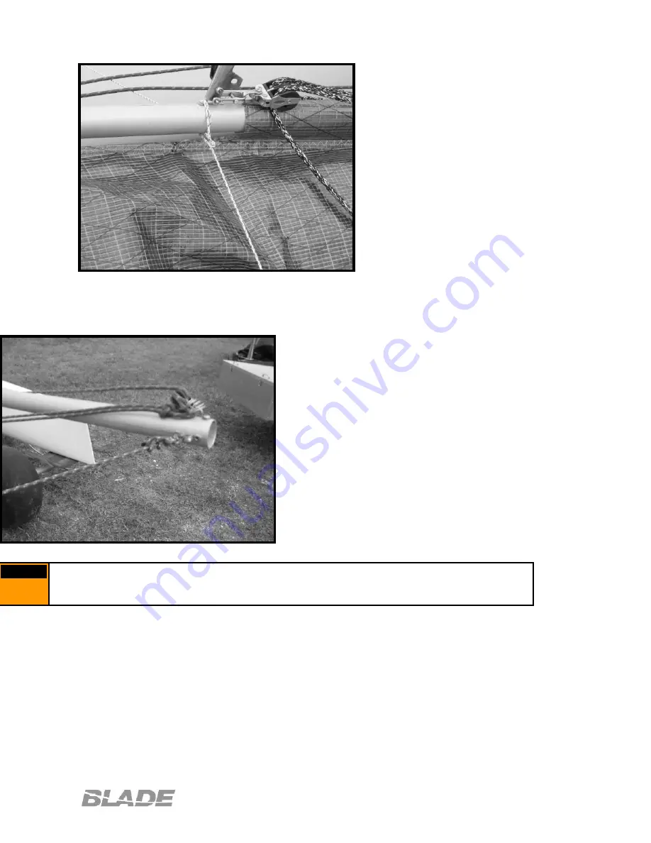
Locate the 4mm lines labeled spin 
bridal.  Tie each of these to the 
outboard end of the spin pole and then 
back to the holes located at the top of 
the bow.  Note: a small section of 
plastic tubing and 3mm spectra have 
been provided to run as a tie loop 
through the bow hole if desired.  The 
bridal should be tied to provide a small 
amount of downward pre-bend in the 
spin pole.  2-4” should be sufficient.  
Too much bend can permanently 
deform the pole, while too little will not 
provide enough support while the 
spinnaker is being flown.   
 

Failure to rig the spin bridal before sailing or before raising the spinnaker will result 
in breaking the spin pole. 


Warning: Failure to rig the spin bridal before sailing or before raising the 

spinnaker will result in breaking the spin pole. 

Warning 

Fig 9.C 

Fig 9.D 

Summary of Contents for Blade F16

Page 1: ...Page 1 Owner s Manual Copyright 2006 Vectorworks Sail 805 Marina Road Titusville FL 32796 USA 321 269 8444 Revision Date 2006 03 17 ...

Page 2: ...of the above listed models Before starting assembly familiarize your self with the contents of the containers and the steps in this manual There are variations between models and may be some minor variations based on model year and options be sure to follow the appropriate procedures where applicable ...

Page 3: ...tem 8 2 Rudder Alignment 9 0 Spin Pole 10 0 Jib Sheet System 10 1 Jib Rotation Limiter 10 2 Jib Sheet 11 0 Boom 12 0 Mast Rotation Mast connection 13 0 Mainsail 13 1 External Downhaul 14 0 Raising the Mainsail 15 0 Lowering the Mainsail 16 0 Mainsheet 17 0 Downhaul 18 0 Outhaul 19 0 Jib 20 0 Spinnaker 20 1 Halyard Run 20 2 Attaching the Spin 21 0 Spin Sheet 22 0 Sailing and Beaching 23 0 Righting ...

Page 4: ...s and picture of them List of required tools List of required Supplies silicone Some parts may vary slightly from what is pictured The exact contents may differ depending on model and options Picture of all the parts with descriptions Fig 1 A ...

Page 5: ...s severe damage could occur to the beams or hulls if they are tightened with the hulls out of alignment Figure 2 A Once the hulls are set remove the bolts from the cross bars and set on the hulls Dry fit the bolts to ensure everything will fit smoothly The hulls were pre assembled in the factory so if they are aligned properly the bolts should slide smoothly into the hulls After you are confident ...

Page 6: ...ets located in the aft outside corner of the tramp Pull the line snug and bring back under the rear cross bar and wrap over the first of the tramp lacing buttons located on the aft side of the cross bar Bring the line forward and wrap over the exposed end of the fiberglass rod and then back to the first lacing button again Pull the line over the top of the first button and string over the top of t...

Page 7: ...e through the turning block provided and back through the center grommet under the tramp and back up through the cleat on the opposite hull Note the turning block will be attached to the line run through the mast rotation arm on the mast after the mast is stepped to control rotation 6 0 Mast Assembly 6 1 Spreaders Attach the spreader arms to the fittings located approximately way up the mast Use t...

Page 8: ...best to tighten the wires when they are not under load to prevent seizing This may take several iterations to get the proper tension and ensure that the mast is straight Once set tighten the jam nut located on the top of the mast base to ensure the wire do not loosen while sailing These setting are a starting point and you will need to adjust them to fit your own sail weight and sailing conditions...

Page 9: ... side of the mast through the spreader arms Keep the spin head end outside of the mast and clear of the standing rigging 6 5 Standing rigging Find the shrouds and forestay wires and attach to the lower hole in the mast hound with the 5 16 bow shackle as shown Note the forestay wire should be placed in between the 2 shroud wires on the shackle Fig 6 D Fig 6 E ...

Page 10: ... to the forestay wire Attach the shroud adjuster on the hulls using a clevis pin as shown 6 6 Pelican striker assembly The bridal wires should attach to the center of the pelican striker tube as shown with a bow shackle The opposite ends of the bridal wires then are fastened to each hull bow tang Ensure the jib attachment tang on the striker tube faces aft Fig 6 F Fig 6 G Fig 6 H ...

Page 11: ...ore you begin to lift the mast One person should stand on the tramp at the rear beam The second person should walk the mast up to the person standing on the tramp They should then raise the mast to their shoulders and walk forward extending their arms pushing the mast into a vertical position with tension on the shrouds At this point rotate the mast 180 degrees back to a normal position and contin...

Page 12: ... the rudder head inside the upper gudgeon and through the turning block located on the top of the transom The line will feed then through a hole located on the aft cross on the hull centerline and out the opposite face through another turning block Loosely run the line inboard along the rear cross bar and attach in the pivot cleat mounted approximately 2 3 of the way inboard Attach the tiller tie ...

Page 13: ...pin hoop on the spin pole into the bottom of the pelican striker tube assembly This will then be pinned in place with the 2 stage halyard shackle Ensure the halyard shackle faces aft when complete and has the 30mm blocks for the jib sheet attached Locate the 3mm lines labeled false bridal Tie each to the spin pole at the pelican striker attachment point Tie the ends to the bridal tang at each hull...

Page 14: ...l should be tied to provide a small amount of downward pre bend in the spin pole 2 4 should be sufficient Too much bend can permanently deform the pole while too little will not provide enough support while the spinnaker is being flown Failure to rig the spin bridal before sailing or before raising the spinnaker will result in breaking the spin pole Warning Failure to rig the spin bridal before sa...

Page 15: ...ard 10 2 Jib Sheet Run the 3mm spec tine through the block now mounted on the jib traveler car Tie a 1 8 bow shackle to the upper side which will be used to connect to the jib clew plate ON the lower side of this line tie the 30mm single block Feed the 6mm jib sheet line first through the pivoting cleat mounted on either of the jib track pylon posts Run this then forward through one of the blocks ...

Page 16: ...the end of the mast rotator arm to the eyelet mounted on the lower boom face When complete the rotation arm should be set approximately parallel to the tramp as to adequately clear the storage pocket 13 0 Mainsail Roll out the mains sail on a clean flat surface Insert the battens into the appropriate pockets Make sure they are inserted fully and lie flat to allow them to go all the way into the ca...

Page 17: ... feeding properly into the sail track while being raised If the luff rope in the sail comes out of the track at the bottom stop lower the sail slightly and continue as before When the sail is fully raised the ring will catch on the halyard hook at the top of the mast Pull firmly on the foot of the sail several times to ensure that the ring is fully attached Coil up the halyard line and tuck into t...

Page 18: ...o each one of the cascading blocks and then feed one of these block through the 5mm main line Continue to feed the main line back through the cheek block mounted at the base of the mast sail track and back up to the other block and 4mm line on the opposite side of the mast This will then go back through the opposite pivot cleat and back onto the tramp The 2 loose ends of the main control line can ...

Page 19: ...ard and feed through 1 of the cheek blocks mounted to the base of the striker assembly and then back up through the small becket block located on the opposite side of the halyard wire This will then be brought down through the opposite cheek block and led back to either of the cam cleats mounted on the front cross bar Gently tension at first and adjust as required while sailing Note the forestay I...

Page 20: ...o back blocks onto the line at this point and bring the line into the spin lock located at the out side edge of the forward cross bar Run the line to the rear cross bar and down through the tramp going through the spin halyard pulley on the aft cross bar Bring the line back under the boat and going through the port side opening between the dolphin striker and the forward beam feed it into the back...

Page 21: ...ase the cams and begin pulling the halyard line from the rear of the boat The sail will snuff into the mid pole hoop With a new sail this may pull a little hard at first Also note when testing on land with a slight head wind or no wind the sails may bunch up on the bridals or around the pole Avoid using excess force to snuff the sail when it may be caught over or under an obstacle as you may rip t...

Page 22: ...carrying more than two persons All inspection ports and drain plugs shall be closed while sailing Bilge water shall be kept at a minimum Do not breach watertight compartments The stability of the craft is reduced when weight is added up high 23 0 Righting after a capsize At some point in your sailing experience you are likely to experience a capsize As an owner familiarize your self with the boat ...

Page 23: ... your weight forward or aft to swing the bows in the proper direction prior to righting With your weight at or just behind the front cross bar grab the righting line and hike out backwards Once the mast tip breaks free of the water the boat will come up very quickly Move your weight inboard to control the speed to the righting boat As it comes over and is falling freely release the righting line a...

Page 24: ...ft end of the mast To protect against rocks gravel and road debris boat covers are recommended They also provide protection from the weather and the elements Mooring of your boat is not recommended Always leave the drain plugs and inspection ports open to avoid the build up of air pressure and causing hull damage when not sailing 25 0 Design Category Design category D Inland coast or protected wat...

Page 25: ...ll Do not use compressed air or power equipment such as vacuum cleaners as they will lover pressurize you hull and damage it Remove leaky fitting clean and reinstall with fresh silicone If the leak is in an area with a fitting this should be reglassed using proper methods to ensure bonding Periodically check all cars cleats and bearings to ensure they run freely Replace the bearings as necessary a...

Reviews: