


TCY-MZ
Technical data
Doc: 70-00-0311 V1.0, 2012-11-09
© Vector Controls GmbH, Switzerland
Page 3
Subject to alteration
www.vectorcontrols.com
Installation and Safety advice
Caution!
This device is intended to be used for comfort applications. Where a device failure endangers human life and/or
property, it is the responsibility of the owner, designer and installer to add additional safety devices to prevent or detect a
system failure caused by such a device failure. Vector Controls or its affiliates cannot be held liable for any damage
caused by such a failure. Failure to follow specifications and local regulations may endanger life, cause equipment damage
and void warranty.
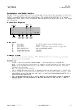
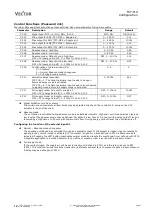
Connection diagram
Description:
G0
Power supply:
0V, -24VDC, internally connected to signal common
G
Power supply:
24VAC, +24VDC
M
Signal common:
Common 0 potential for analog inputs and analog outputs.
X1
External passive input:
open contact to signal common
U1
Analog output supply air:
0…10 V DC
U2
Analog output return air:
0…10 V DC
Mounting location
On an easy accessible interior wall, approx. 1.5 m (4.5’) above the floor in an area of average temperature.
Avoid exposure to direct sunlight
Installation
1.
Connect the wires to be connected to the terminals of the power case according to wiring diagram
2.
Install the mounting plate to the flush mounting box. Make sure that the nipple with the front holding screw is
facing to the ground. Make sure the mounting screw heads do not stand out more than 5 mm (0.2”) off the
surface of the mounting plate.
3.
Ensure that the jumpers are set correctly.
4.
Slide the two latches located on the top of the front part into the hooks at the upper side of the mounting plate.
5.
Carefully lower the front part until the interconnector reaches the mounting-plate. Continue pressing in a gentle
way until the front part is fully connected. While inserting the connectors, a slight resistance can be felt. This is
normal. Do not use excessive force!
6.
With a Philips-type screw driver of size #2, carefully tighten the front holding screw to secure the front part to
the mounting plate. This screw is located on the front lower side of the unit. There is no need to tighten the
screw too much.
0V (COM)
24V AC/DC
2
G
TCY-MZ2
1
G0
3
M
Signal
COM
4
U1
Supply
OUT
7
M
Signal
COM
8
X1
X
1
IN
5
M
Signal
COM
6
U2
Return
OUT


