background image


X2-O

PERATIONS 

M

ANUAL 

T

OUCH 

D

ISPLAY


Doc: 70-07-0951A, 20220504  

© Vector Controls LLC, USA 

Page 9-18 

Subjects to alteration 

www.vectorcontrols.com 

V

ECTOR


5


Extended Operating Level 

5.1


Clock Operation 

Overview 

This section gives an overview of the clock and the available timed functions of the X2 controller. 


Note on Accuracy 


Warning: The TCX2-40863 and X2 devices with a "C" addition (e.g. TRI2-FU-TH-221.202

C

) have a real-time clock. 

This clock is accurate to two seconds a day. 
Other TCX2 series devices may have no time functions or if they do, they calculate the time based on the 

processor's internal clock speed. This time source is accurate to approx. 2 minutes per day. If the controller uses its 

time program functions, it is therefore necessary to synchronize the time of these controllers at least every 24 

hours with an exact time base. 


Time Programs 


The TCX2-40863 and devices with a "C" addition (e.g. TRI2-FU-TH-221.202

C

) have a real-time clock with a 

maintenance-free power backup. 

Up to 12 time and weekday programs or annual holidays can be programmed (Pr01 to Pr12). Schedules can change the 

operating mode of the controller (on, off, occupied, unoccupied), change the fan status, position an output directly or change 

a setpoint. 
The summer/winter time changeover can be activated by the technician via user parameters. 

A flashing clock 

 indicates that the time has not been set or that the terminal has been without power for more than 48 

hours. The time must be set for the schedules to work. 


5.2


Clock Setting 

5.2.1


Setting time and date of clock 

Overview 

This section describes how to set the time and date of the X2 system clock. 

Procedure 


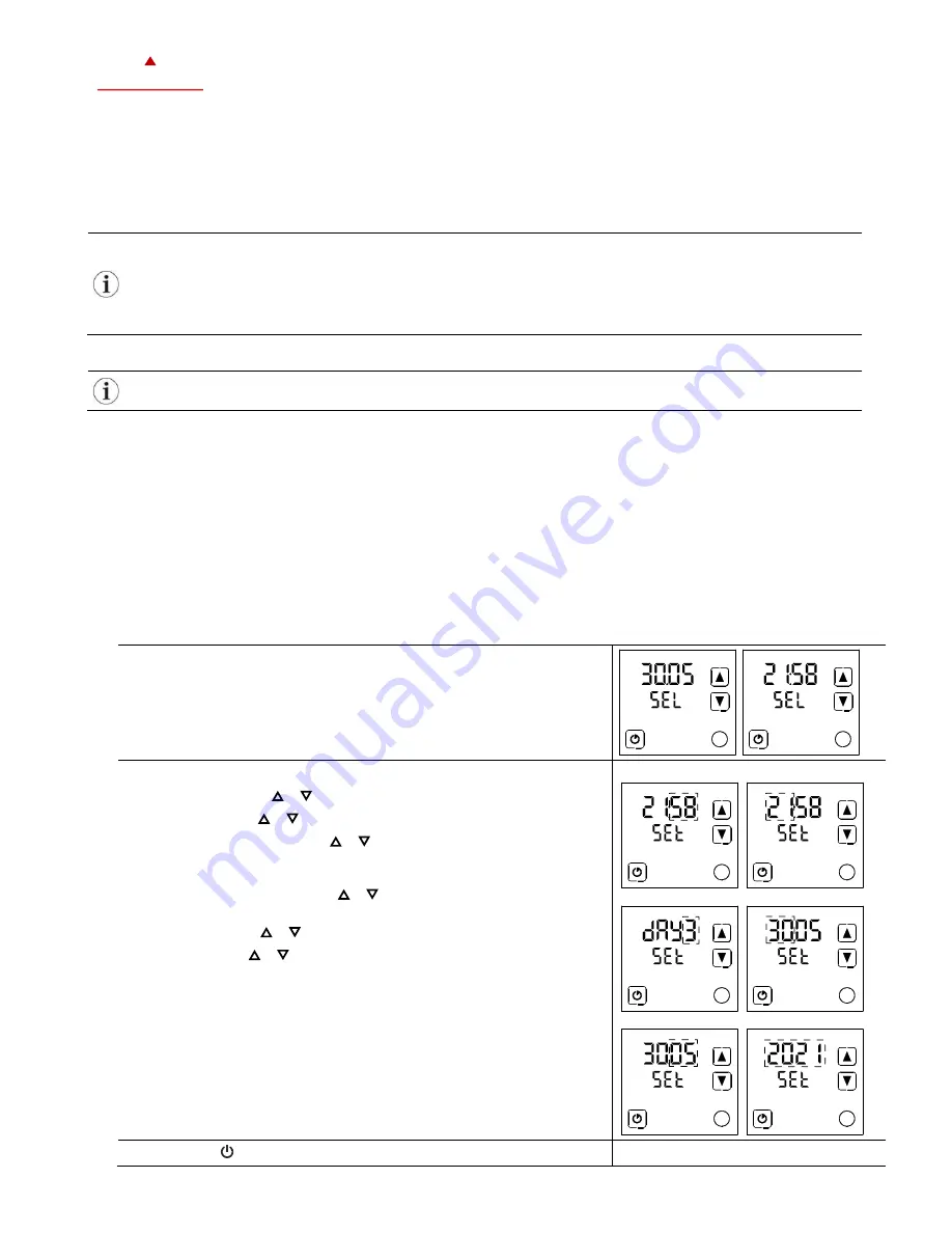
1.


Press the (

) button longer than 2 seconds. 


SEL

 and the actual 

Date

 and 

Time

 are displayed alternatingly. 


2.


Press the (

) button briefly to start changing the time and date: 

Minutes

 flashes: ( ) ( ) button for adjustment, (

) button to save. 

Hours

 flashes: ( ) ( ) button for adjustment, (

) button to save. 

Day of the week

 flashes: ( ) ( ) button for adjustment, (

) button 

to save. 

Note: Monday is day 1 of the week. 

Day of the month

 flashes: ( ) ( ) button for adjustment, (

button to save. 

Month

 flashes: ( ) ( ) button for adjustment, (

) button to save. 

Year

 flashes: ( ) ( ) button for adjustment, (

) button to save. 

Set Minutes 

Set Hours 


Set Day of Week 

Set Day of Month 


Set Month 

Set Year 


Press the ( ) button (1x) to go back to the previous submenu. 


Summary of Contents for TRI2 Series

Page 1: ...tions for entire buildings There is a suitable solution for almost every application With the EasySet program the controllers can be conveniently read out programmed and transferred to other controlle...

Page 2: ...rating levels 2 Display and Operation 2 1 User Interface 2 1 1 OPT1 TRI2 series X2 devices Figure 1 OPT1 TRI2 Button Symbol Function Description Operating mode Back Operating mode selection On Off Occ...

Page 3: ...ve 4 Fan auto mode Fan speed is automatically regulated by the controller 5 Operating Mode See chapter 2 3 6 Touch buttons See chapter 2 1 1 7 8 Large digits Small digits The large and small digits ar...

Page 4: ...isplay Status Description Alarm Alarm Error active see chapter 2 6 and 2 7 LED on flashing Normal Status LED is on or blinks briefly once every 5 seconds LED blinking Alarm Error Status LED blinks eve...

Page 5: ...r An assigned input is not activated or has failed Check all settings and ensure that all inputs used are activated and functional For TRI2 this error will show if the front panel was removed with the...

Page 6: ...a control loop The large digits show the input value The small digits show the set point Horizontal bars top left show which loop is being displayed It is possible to omit the display of the current v...

Page 7: ...an annual time schedule is active the X2 device runs in standby The system is protected against overheating and frost if enabled Inputs are monitored for alarms 3 7 Power Failure All parameters and s...

Page 8: ...to change the fan speed The side bar indicates the actual fan speed The fan speed will alternate between FSP0 FSP1 FSP2 FSP3 AUTO FSP0 FSP0 may be disabled by settings the number of available fan spe...

Page 9: ...mmed Pr01 to Pr12 Schedules can change the operating mode of the controller on off occupied unoccupied change the fan status position an output directly or change a setpoint The summer winter time cha...

Page 10: ...ble Overview This section describes how to generally enable disable timed events schedules on a X2 device Procedure 1 Press the button longer than 2 seconds SEL and the actual Date and Time are displa...

Page 11: ...s OFF or ON 4 Press the button to change the status When scheduler is ON is displayed 5 Press the or button to select between programs Pr 01 Pr 12 6 Press the button and assign one of the following fu...

Page 12: ...ing on function selected in instruction No 6 a OP operating mode ON Occupied normal operation ECO Unoccupied reduced operation OFF protective operation b LP control loop set point LP01 LP0x C F c AO a...

Page 13: ...e and Time are displayed alternatingly 2 Press the button briefly to go to the scheduler submenu PRO and SEL is displayed 3 Press the button Schedule status indicates whether it is OFF or ON 4 Press t...

Page 14: ...s with the button 3 bars indicate setting step 3 is executed 9 Press the button and adjust the month the holiday ends with the button 4 bars indicate setting step 4 is executed 10 Press the button and...

Page 15: ...e button and select one of the following functions Cooling Cooling only The controller stays in cooling mode only and will not switch to heating Fan only cooling The controller is in fan only mode The...

Page 16: ...r button until the universal input submenu UI and SEL is displayed U I and SEL is displayed 3 Press the button and select one of the universal inputs with the button U I the input number and the value...

Page 17: ...ith the button do the output number and the value are displayed 4 Press the button again do the output number and the total runtime of the output are displayed If the runtime is greater than 9999 hour...

Page 18: ...0951A 20220504 Vector Controls LLC USA Page 18 18 Subjects to alteration www vectorcontrols com VECTOR Smart Sensors and Controls Made Easy Quality Innovation Partnership Vector Controls LLC USA info...

Reviews: