


32
©Vecow EMBC-5000 User Manual
GETTING TO KNOW YOUR EMBC-5000
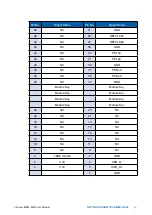
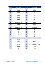
2.2.21 JDIO1, JDIO2 : GPIO from Super I/O
There is a 16-bit GPIO connector in the Top side. Each GPIO channel can be
configuration GPI or GPO.
JSEL_DIO header is for SYNC/SOURCE mode selection on ISO_DIO board
(DMX-100-E)
JDIO1 and JDIO2 pins are defined in the following table :
Pin No.
JDIO1 Definition
JDIO2 Definition
1
SIO_GPI80
SIO_GPO70
2
SIO_GPI81
SIO_GPO71
3
SIO_GPI82
SIO_GPO72
4
SIO_GPI83
SIO_GPO73
5
SIO_GPI84
SIO_GPO74
6
SIO_GPI85
SIO_GPO75
7
SIO_GPI86
SIO_GPO76
8
SIO_GPI87
SIO_GPO77
9
+VDIO
+VDIO
10
GND
GND
1
10
Y
L1
1
R10
R9
7
1
7
1
6
A2
A52
B2
B52
10
10
10
10
A1
A51
10
B1
B51
3
1
10
1
10
1
1
4
2
10
1
L2
1
1
1
1
7
3
1
Y
L1
R10
R9
10
1
1
L4
G
O
L3
R1
R2
2
1
1
8
4
5
3
1
39
40
10
9
1
18
4
13
5
14
L4
G
R1
R2
O
L3
1
2
L2
2
10
20
19
1
9
1
4
1 3
259
145
143
1
2
1
146
144
260
2
20
19
JDIO1
JDIO2
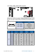
2.2.22 SW2 : RESET Button
U29
C3
C7
C2
C5 SW C6
C1
53
42
32
22
11
DW
BY
AY
Y
A
1
97
128
3
1
96
1
2
1
3
65
64
32
33
2
15
1
3
2
43
29 28
1
2 3
1
2
4
3
M2B_SIM1
CPU1
M2E_LED1
M2B_LED1
LED2
LAN2
LED1
SW2
SW2
Pin assignment as the following table :
Pin No.
Definition
Pin No.
Definition
1
FP_RST_BTN_N
2
GND
3
FP_RST_BTN_N
4
GND
4
1
2
3


