


LVP615U
使用说明
51
LOOP
LOOP
DVI
LOOP
LVP615U#0
#1
#2
#4
#3
Input signals
LVP615U#
LVP615U#
LVP615U#
LVP615U#
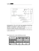
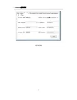
System Topology
3456
1920
As above diagram shows, all input signals are connected to and switched by
#0 LVP615U
. The 2 same DVI outputs of
#0 LVP615U
are connect to
#1
LVP615U
and
#2 LVP615U
. Then
DVI loop
to
#3
and
#4
.
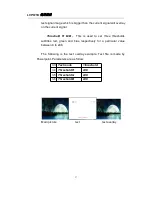
After that, the output signal of #0 LVP615U is cropped and scale up in #1
LVP615U, #2 LVP615U, #3 LVP615U and #4 LVP615U.
Finally the image that they output will be finally displayed as a whole picture on
4 pieces of LED screens.
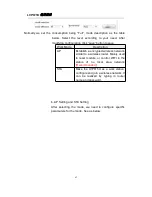
The parameters of the 4 units of LVP615U are as below:
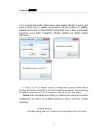
Setup options
Parameter setups of processor
#1
#2
#3
#4
E.1 LED total width
3456
E.2 LED total height
1920
E.4 Unit width
1728
1728
1728
1728
E.5 Unit height
960
960
960
960
E.6 Unit horizontal
start
0
1728
0
1728
Summary of Contents for LVP615U
Page 1: ...LVP615U LED HD Video Processor User Manual V1 0...
Page 9: ...LVP615U 9 3 4 Specifications...
Page 13: ...LVP615U 13 RS232 cable order...
Page 63: ...LVP615U 63 AP setting...
Page 88: ...LVP615U 88 2 APP Operation...
Page 91: ...LVP615U 91...
Page 94: ...LVP615U 94...
Page 95: ...LVP615U 95 2 PIP Display...
Page 101: ...LVP615U 101 1 Output Resolution...
Page 104: ...LVP615U 104 4 Image quality...
Page 112: ...LVP615U 112...


