


LVP606A User’s Manual
---------------------------------------------------------------------------------------------------
LED VIDEO PROCESSOR
18
some bad phenomena, such as color cast, extreme-darkness.
LVP606A
can solve the above problems by automatically calibrating
white balance based on the input analog signals (
CVBS
,
VGA
).
Operating procedures:
Switch to the corresponding analog input signal, enter Item No. 47
after the processor detects input signals and exports the signals to the
display, press the knob to calibrate white balance.
Caution: The white balance of all video processors has been
calibrated using standard signals in the factory, please don’t set
this item unless necessary!
Item 48: “
Device Init”
After entering item No.45, press “
Preselect V1
” for 5 times, then
press “
↑
” to move to Item No.48:
“Device Init”
,
turn the knob to select
“Yes”, then press the knob( “
Save
”) to reset the factory settings, the
moment the system will remind you
“Please restart.”
, just follow the
instruction.
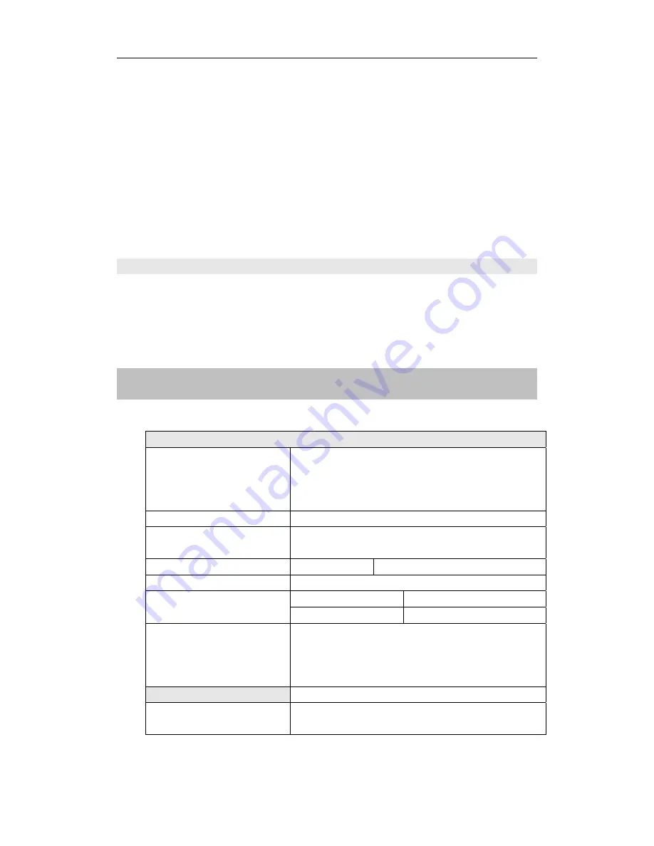
VI. Specifications
Inputs
Nums/Type 2×Composite
video
2×VGA (RGBHV)
1×DVI / HDMI
2×DVI-I(VGA/DVI/HDMI)
Video System
PAL/NTSC
Composite Video
Scope/Impedance
1V (p_p) / 75
Ω
VGA Format
PC (VESA)
≤
1600x1200 @60HZ
VGA Scope/Impedance
R, G, B = 0.7 V (p_p) / 75
Ω
DVI / HDMI Format
( HDCP )
SD/HD(EIA-861B)
≤
1920x1080P @60HZ
PC(VESA)
≤
1600x1200 @60HZ
Input Connectors
VGA
:
15pin D_Sub(Female)
DVI
:
24+1 DVI_D
DVI-I: 24+5 DVI_I
Composite video
:
BNC
Outputs
Nums/Type 2×DVI
1×VGA (RGBHV)