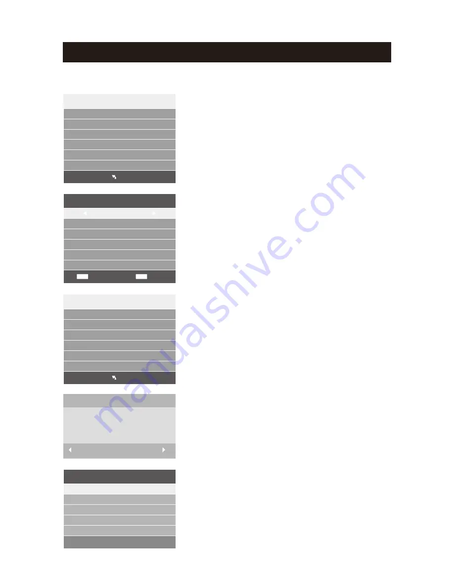
PVR settings
Warning! ALL data will be lost.
Format disk
Format disk
4)
Format
:
At
Format stage
,
press
ENTER
button
to
start
formatting the USB.
Check
storage
equipment
PVR
File
System
is
well
established
.
Press ENTER
button
to
inspect
the
USB files
system
and
speed
,
the
processing
shows
Checking
…
;
When
USB is not inserted
, or
inspection
failed
,
it
shows
FAIL;
When USB is inserted but
didn
’
t
be formatted
, enter
Format
menu;
If
inspection
is
normal
,
it
shows
SUCCESS.
3) Check
PVR
File
System
:
Choose the
disc
to
store
whatever
content
need
record
.
As follows, default as C.
NOTE: please format your hard disk before use the
PVR function for the first time.
Select Disk
Disk C:
USB 0
2) Select Disk
Setup the PVR File system before you start recording.
Select Disk
Check PVR File System Start
Menu
USB Disk
Format
Time Shift Size
Speed
C:
Free Record Limit 3Hr.
1) Recorder System
Select
Disk
:
Select the device for the Record files.
Check
PVR
File
System
USB
Disk
:
Display the USB state.
Format
:
Format the USB device for PVR operating.
Time
Shift
Size
:
Display the recording size of the USB device.
Speed
:
Display the recording speed of the USB device
.
(The device has been formatted).
(The device has been formatted.
Free Record Limit:
Display the free record limit of USB
device. (The device has been formatted).
When
finish
Creating
PVR
file
system
,
it
pop
out
Time
Shift
Size
setting
menu
,
and
clients
can
set
the
space
size
for
time
shift
as
follows
.
5) File System Size
PVR File System Type FAT32
SD 104 Mins
HD 29 Mins
Record Function (Only in DTV mode)
44
After Formatting, the PVR File system is built.
PVR File system is being built at this stage, during the USB
recognition process, the OSD media reminds user not to
plug out the USB.
Select
ENTER
Back
MENU
Select Disk
Check PVR File System
SUCCESS
Menu
USB Disk
Format
Time Shift Size
Speed
C:
Free Record Limit
3Hr.
Pas s
Pas s
All
S D
F A IL
0
KB
/
S
Start
Exit
File System Size
PVR File System Size All
Summary of Contents for 32LEDS992
Page 1: ......
Page 2: ...1 2 4 6 7 8 9 10 12 13 14 17 17 18 19 23 1 18 22 5 PC 15 EPG 16...
Page 3: ...2 AC V DIGI AC AC V DIGI AC AC 110 240V AC AC AC AC AC AC...
Page 4: ...3 AC AC AC AC AC AC AC AC AC AC AC AC AC...
Page 5: ...4 AC V DIGI AC AC LED 99 99 LED LED LED LED AC AC...
Page 6: ...5 M4 12mm 3pcs M4 12mm 3 M6 M6...
Page 8: ...7...
Page 9: ...8 TV TV...
Page 11: ...3 ENTER 2 1 MENU 1 ENTER 2 MENU EXIT 3 10 2 0 0 TV 0 MENU 81 25 MHz ENTER MENU EXIT...
Page 13: ...3 ENTER 2 1 MENU 12 ENTER MENU EXIT...
Page 14: ...3 ENTER 2 1 MENU 3 ENTER 2 1 MENU 13 ENTER PCM ENTER MENU EXIT ENTER MENU EXIT...
Page 16: ...15 ENTER MENU EXIT...
Page 22: ...ENTER PVR 1 USB 1G 2 USB USB 3 PVR DTV 4 PVR 5 PVR 6 6 USB USB2 0 7 PVR 21...
Page 24: ...23...
Page 25: ...24...
Page 31: ...30 3 3pcs M4 12mm M4 12mm...
Page 33: ...32 Remote Control Sensor and Power Standby Indicator...
Page 34: ...33 TV TV...
Page 50: ...49...
Page 51: ......


