background image

Operating this equipment: 

To place your press into service — 

1.)  Follow the assembly instructions on pages 4 through 12. 

To operate your press — 

1.)  Clamp your first screen into head #1. 

2.)  Repeat for additional screens, using additional heads. 

3.)  Place garment in pallet #1. 

4.)  Lower print head and squeegee ink through screen. 

5.)  Raise print head.  For one-color printing, load new, blank garment and repeat steps above. 

6.)  For multi-color printing, rotate the pallet to print head #2 and repeat steps above until all colors are printed. 

7.)  If any adjustments to the print heads need to be made, refer to the instructions in this manual. 

Safe handling, transport, and storage of the press:


Your press is designed to be inherently safe under all normal conditions.  When handling or transporting your 
press, be aware of the weight of your unit and have an appropriate number of people to lift the weight safely:  


V100-11: 65lb (29.5kg) 

V100-44: 132lb (59.9kg) 

In the event of an accident or breakdown: 

In the unlikely event that a part of your press breaks, or if your press does not seem to be operating normally and 
the instructions in this manual do not correct the issue, do not continue using your press.  Contact Vastex for as-
sistance in repairing your press. 

Safety during maintenance or while making adjustments: 

 

When cleaning or lubricating your press, make sure that nobody in the work area is close enough to cause 
any part of the press to move unexpectedly.   

 

Do not remove springs unless under the specific direction of Vastex customer service. 

 

Observe the general safety cautions on page 2 of this manual. 

Placing this equipment into service: 

Stability during use, transportation, assembly, foreseeable breakdowns, etc.:


This equipment is designed and expected to be stable during all normal conditions of use.   

 

When assembling your press, do not stand tall parts upright until you are ready to install them; lay them flat 
instead.   

 

It is recommended that assembly should be done by two or more people, to facilitate the alignment of parts 
that must be bolted together. 

 

If one or more legs of the press will be removed, be certain to adequately support the rest of the press.


Pg.3

Summary of Contents for V-100

Page 1: ...Pallet Assembly 10 11 Print Head Assembly 12 13 Machine Adjustments 14 Warranty 15 Serial Number Please log your machine s serial number and date of purchase for future reference Date ____ ____ _____...

Page 2: ...intended for performing manual screen printing of fabric items particularly garments This equip ment must not be used in a manner contrary to what is described in this manual Safety The operator shoul...

Page 3: ...e unlikely event that a part of your press breaks or if your press does not seem to be operating normally and the instructions in this manual do not correct the issue do not continue using your press...

Page 4: ...all and Tighten 1 1 2 13 x 1 0 Bolt 1 1 2 Lock Washer Use 3 4 or adjustable wrench 1 Line up Notches 2 Install and Leave Loose 4 5 16 18 x 3 4 Bolts 4 5 16 18 Lock Nuts Do not tighten until STEP 5 5 T...

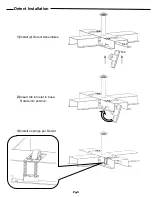
Page 5: ...Detent Installation 1 Install 2 Detent Assemblies 2 Insert tab into slot in base Rotate into position Tab Slot 3 Install 2 springs per Detent Pg 5...

Page 6: ...ing 1 2 or 13mm Wrench 2 Install and leave loose 8 5 16 18 x 3 0 bolts 8 5 16 18 lock nuts For 1 station tighten 3 sets For 4 station leave all outer bolts loose Using 1 2 or 13mm Wrench 1 Install and...

Page 7: ...all and Leave Loose 2 5 16 18 x 2 1 4 Bolts 2 5 16 18 Lock Nuts Install all included hinges at this time Do Not Tighten until Hub Installation Step 3 1 color Hub Shown Below 4 color Hub Shown Below Ta...

Page 8: ...Washer 2x 1 2 Washer 1 2 20 x 1 0 Bolt Bearings 2x Bearing 2 Tighten top 1 2 20 x 1 0 Bolt using a 3 4 or 19mm open end wrench Do not Over Tighten Only tighten until there is drag on the hubs when sp...

Page 9: ...or Arm to be installed 3 Align Rotor Arm with Bolts in Rotor Hub Tabs on bottom of Rotor Arm drop into slots in Bottom Rotor Hub Plate 4 Install and Tighten 4 5 16 18 Lock Nuts 2 5 16 18 x 1 2 Bolts U...

Page 10: ...ck Nuts Using 1 2 or 13mm wrench 2 Install 1 5 16 18 T Weldnut 1 Pallet Arm knob 3 Insert Corner Clamp Bracket 4 Install Angel Clip 5 Install 4 5 16 18 x 1 0 Square head Bolts 6 Install and Tighten 1...

Page 11: ...let Installation 1 Slide your assembled Pallet and Pallet Arm onto Rotor Arm 2 Set each pallet the same Use slots on side of Rotor Arm for reference 3 Tighten knob on Pallet Arm Do not over tighten Pg...

Page 12: ...arriage Bolts 2 5 16 Flat Washers 2 5 16 18 Lock Nuts 1 Assembled Screen Clamp Using 1 2 or 13mm Wrench 1 Install and Tighten 4 5 16 18 x 3 4 Bolts 2 5 16 Flat Washers 2 Double 5 16 18 Nuts 1 Screen C...

Page 13: ...Install Print heads as shown 2 Attach Springs 4 Install Stop Bar as shown Stop Bar must be installed while head is in the Down position 3 Attach Springs Heavy Note Spring Location Options Orientation...

Page 14: ...Loosen 1 Nut Marked A Slightly and Set Screen Level Adjust one side at a time 1 2 or 13mm Wrench needed Machine Adjustments To Adjust Screen angle Front to Back Loosen 2 Bolts Marked B Slightly and S...

Page 15: ...ensed trucker shall constitute delivery to Buyer and be determinative of the date and time of shipment and all risk of loss or damage in transit shall be borne by Buyer If the Buyer fails to accept th...

Reviews: