4 SAFETY AND ACCIDENT PREVENTION INFORMATION
When working near the pump, dress appropriately, avoiding clothing with loose items (ties,
scarves, etc.) which could get caught in moving parts. Use overalls made according to
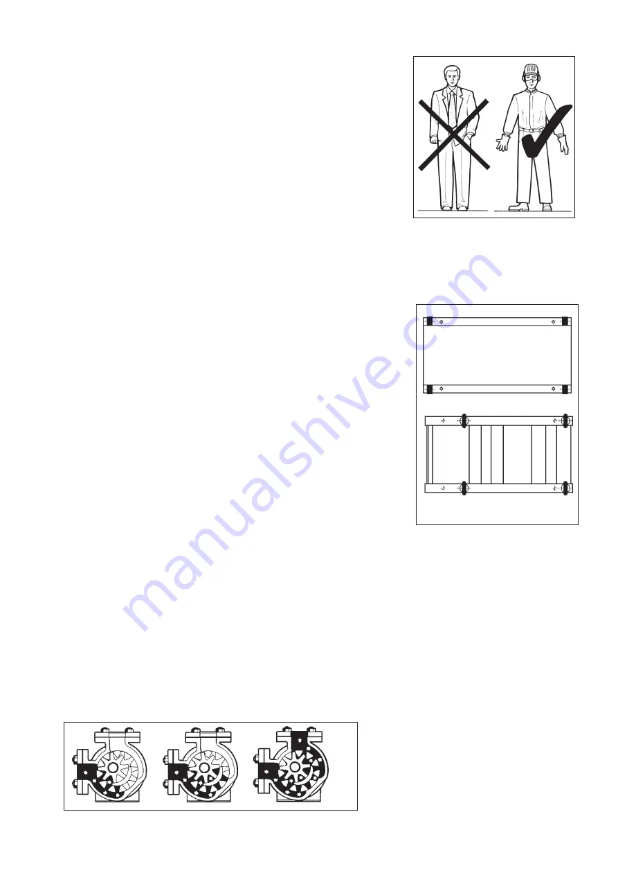
safety regulations, gloves, insulating shoes, safety glasses, ear plugs and helmet (fig.1).
Do not carry out maintenance on the motor while it is running. Keep hands away from
moving parts (e.g. belt, couplings, etc) Keep hands away from the hot areas of the
engine. Do not stand onto the pump in order to carry out any
maintenance operations of any kind.
VARISCO MAGNETIC DRIVE TYPE PUMPS UTILISE HIGH INTENSITY
RANGE MAGNETS. MAINTENANCE OF THESE PUMPS IS, THEREFORE,
NOT RECOMMENDED FOR USERS OF PACEMAKERS
5 IN CASE OF EMERGENCY
Shut down the motor.
Notify the person in charge of running the plant immediately.
6 HANDLING AND TRANSPORT
6.1 Method of transport
The pump must be transported in the horizontal position and stowed safely6
6.2 Hook-on
During the hook-on and maintenance operations, it is important to ensure adequate
transport and handling techniques are used and that these employ appropriate hoisting. In
order to avoid damage to the pump or injury to personnel, all movement and handling must
be performed by specialised personnel.
The lifting rings of the various components must be utilised exclusively to lift those
components.
In figure 2, the lifting points of some basements are indicated in bold..
Maximum lifting velocity : V
max
≤≤
0,5 m/s
7 CONSTRUCTION AND FUNCTIONING
The series V-TRM are magnetic drive type volumetric pumps which are a mono block
construction version with a stainless steel and cast iron support.
The main characteristics of these pumps is the magnetic type transmission. The external
magnetic nucleus (847.1) (see figure 7 of Page 11) connected to the crank shaft (213)
transmits the torque to the internal magnetic nucleus
—
rotor (02), the magnetic field
generates the rotation of the rotor without physical contact. A glass (151) is positioned
between the two nuclei which hermetically seal the liquid pumped from the atmosphere (see
figure 7 Page 9).
The design of the pump was performed in collaboration with CDR Pompe, a company which
has been present in the market for over 20 years and is leader in the design and
manufacture of drive components.
fig. 1
5
fig. 2
!
!
8
INSTALLATION
8.1
The pumps are tested and regulated with a liquid which also serves to protect the internal surfaces for six months from the date of
shipment.
This liquid is a mixture of oil and passive neutral detergent; if this liquid can pollute the product that is to be pumped, it is necessary to
wash out the pump before installation
Do not pump water for any reason or leave traces of water in the casing.
8.2
Install the pump as close as possible to the source of liquid that is to be pumped, leaving sufficient space for inspection and
maintenance access. In particular, space is required in front of the pump in order to remove the cover, near the gland for replacing the
packaging, near the oil discharge plug of the gear box (if fitted) and on the terminal box side of the electric motor.
8.3
Identify the suction and discharge ports before installation. V series pumps are totally reversible: the direction of flow can be inverted by
changing the direction of rotation of the shaft. This means that the suction and discharge ports are not fixed at the outset but can be
interchanges. If a by-pass relief valve is fitted, however, it will operate in only one direction of flow (see paragraph 7.4).
Figure 3 shows the flow path of the liquid inside the
pump; as the gears open, liquid is drawn into the pump
through the disjoints of the teeth in between the rotors
which are, therefore, in proximity the suction port. The
liquid is carried between the gears and the crescent and
is expelled from the discharge port as the gears mesh
during the rejoining phase of the teeth.
fig.3


