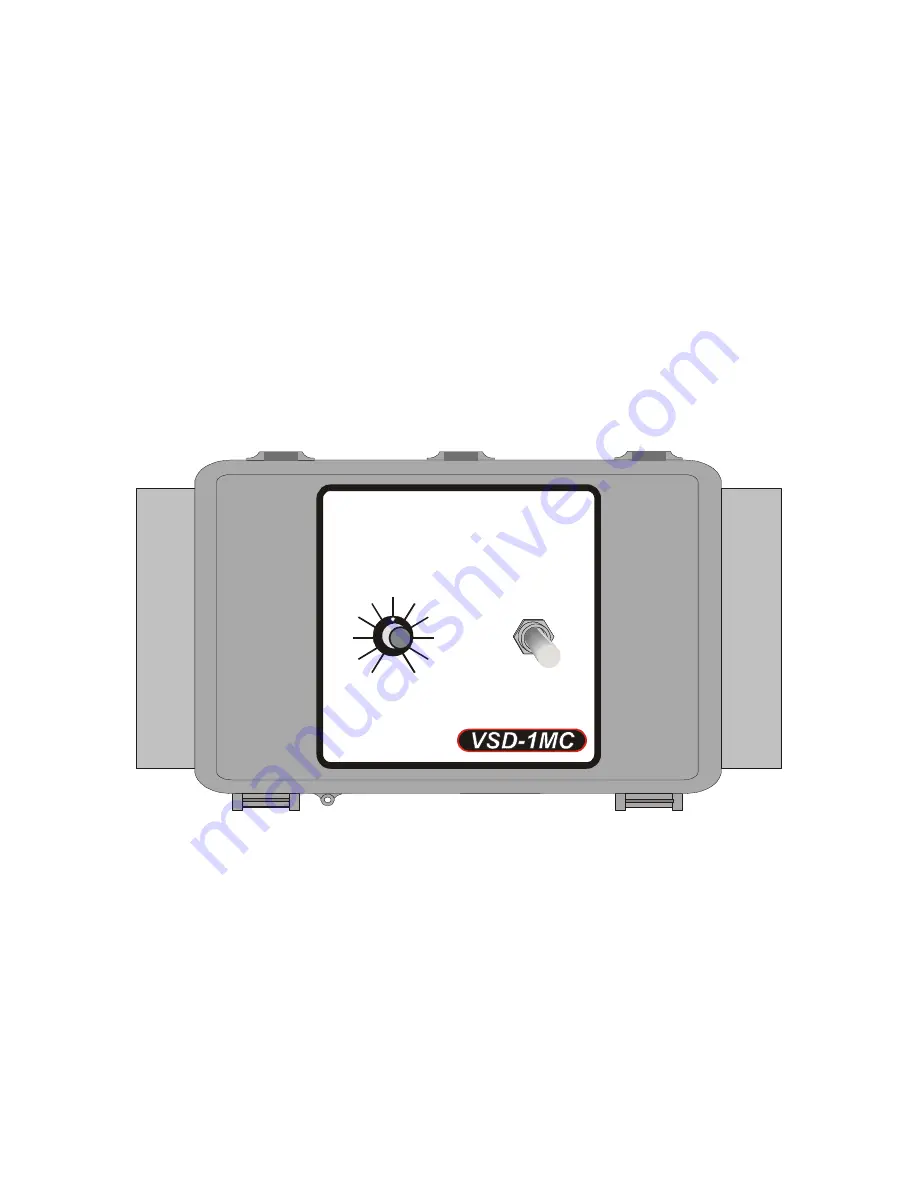
VSD-1MC-20(40)
MANUAL
0-10V / 4-20mA
Variable Speed Module
with Manual Override
Installation / User’s Guide
®
Varifan
AUTO
OFF
1
2
3
4
5
6
7
8
9
10
SPEED
Page 1: ...VSD 1MC 20 40 MANUAL 0 10V 4 20mA Variable Speed Module with Manual Override Installation User s Guide Varifan MANUAL AUTO OFF 1 2 3 4 5 6 7 8 9 10 MANUAL SPEED...
Page 2: ...The VSD 1MC is offered in 3 different models which are VSD 1MC VSD 1MC 20 or VSD 1MC 40 This manual covers the VSD 1MC 20 and VSD 1MC 40 The module operates on 115 230V and 50 60Hz The VSD 1MC 20 40...
Page 3: ...The variable output requires the same phase and same voltage as the controller to operate 4 Connect the power source to the 2 black terminal block identified as LINE as shown in figure 1 5 Set the JP...
Page 4: ...on or troubleshooting a Make sure that the Voltage Selector switch is set to the correct voltage before powering up the module a The variable output requires the same phase and same voltage as the con...
Page 5: ...the input signal is at its minimum value 2 Dip Switches Input Range Switch and Shutoff 5 Switch Dip Switch 1 is used to select the Input Range ON 2 10 Volts 4 20 mA OFF 0 10 Volts 0 20 mA Dip Switch...
Page 6: ...O MANUAL Switch is set to MANUAL The variable output will shutoff is the Manual Speed Selector is turned completely counter clockwise OFF 2 AUTO MANUAL Switch This switch is used to select if the vari...
Page 7: ...of the differential Also refer to figure 2 for the location of the Shutoff 5 Switch Another switch also located on the electronic board will select if the input is a 0 10 Volts 0 20 mA or a 2 10 Volt...
Page 8: ...E Switch 1 OFF 0 10 Volts or 0 20 mA Switch 2 OFF No shutoff at 5 Fan Speed 100 Minimum Speed 10 Volts or 20 mA Input 0 AUTO MODE Switch 1 ON 2 10 Volts or 4 20 mA Switch 2 OFF No shutoff at 5 Fan Spe...
Page 9: ...2 ON Shutoff at 5 Fan Speed 100 Minimum Speed 10 Volts or 20 mA Input 0 0 7 Volts or 1 4 mA 0 5 Volts or 1 mA AUTO MODE Switch 1 ON 2 10 Volts or 4 20 mA Switch 2 ON Shutoff at 5 Fan Speed 100 Minimu...
Page 10: ...VSD 1MC 20 40 Page 10 Figure 5 Logic Diagram Manual Mode MANUAL MODE Switch 1 and Switch 2 are not used in manual mode Fan Speed 100 Minimum Speed 10 100 Faceplate Potentiometer 0 0 7 7 0 5 5...
Page 11: ...13 3 4 x 7 14 16 x 6 1 4 35 cm x 20 cm x 16 cm Warranty 2 years POWER SUPPLY Operational voltage range SW1 115V 92 to 125 VAC Operational voltage range SW1 230V 184 to 250 VAC Operational frequency ra...
Page 12: ...f God flood fire hail or any other natural disaster Any unauthorized work modification or repair on this product automatically voids the warranty and disclaims the manufacturer from all responsibility...
Page 13: ...VSD 1MC 20 40 VER 1 0 November 17 2011...