background image

MVS-1C 

Page 3 

General installation guidelines 

-


It  is  recommended  to  install  the  unit  in  a  hallway  to  limit  the  MVS-1C  exposure  to 
noxious gases. 

-


In  order  to  avoid  condensation  problems  inside  the  MVS-1C,  it  is  recommended  to 
install the module on an inside wall. If it is not possible, use spacers to have an air 
gap between the wall and the controller. 

-


The  MVS-1C  should  be  installed  in  easy-access  location  but  away  from  damaging 
elements (heat, cold, water, direct sunlight…).  

-


Do  not  install  the  MVS-1C  near  high-voltage  equipment,  power  supply  or 
transformer.


-


When  installing the mounting  plates  onto the  back  of the  enclosure, makes sure to 
use a regular screw driver (DO NOT use a drill or electric screw driver) to screw the 
tap screws into the plastic holes.
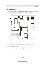


Wiring Procedure 


1.  Open the MVS-1C controller enclosure. 

2.  Verify the technical specifications to know which wire to use. 

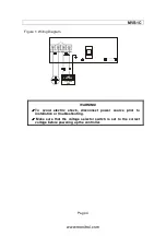
3.  Connect the equipment to the 2 black terminal block identified as FAN as shown 

in figure 1. 


4.  Connect  the  power  source  to  the  2  black  terminal  block  identified  as  LINE  as 

shown in figure 1. 

5.  Make  sure  that  the  voltage  selector  switch  is  set  to  the  correct  voltage  before 

powering up the MVS-1C (refer to figure 2 for the location of the switch). 

6.  Power up the MVS-1C controller. Verify that the controller operates correctly. 

7. 

Close the MVS-1C enclosure. Don’t forget to put a security screw or a padlock.


www.monitrol.com

Summary of Contents for MVS-1C

Page 1: ...MANUAL MVS 1C Manual Variable Speed Control Installation User s Guide www monitrol com ...

Page 2: ...lso turn off the output by turning it counter clockwise The controller operates on 115 230V and 50 60Hz The MVS 1C comes in a PVC non corrosive enclosure that is protected from dust and humidity The MVS 1C is covered by a complete two year warranty Unpacking Unpack the MVS 1C module and inspect contents for damage Should the contents appear to be damaged contact your local distributor to return th...

Page 3: ...e back of the enclosure makes sure to use a regular screw driver DO NOT use a drill or electric screw driver to screw the tap screws into the plastic holes Wiring Procedure 1 Open the MVS 1C controller enclosure 2 Verify the technical specifications to know which wire to use 3 Connect the equipment to the 2 black terminal block identified as FAN as shown in figure 1 4 Connect the power source to t...

Page 4: ...NG To avoid electric shock disconnect power source prior to installation or troubleshooting Make sure that the voltage selector switch is set to the correct voltage before powering up the controller 230V LINE VOLTAGE 115 230 VAC www monitrol com ...

Page 5: ...Figure 2 Electronic Board and component location 15A 250V 230V FAN LINE 115 230V 1341 A REV 2 1 Minimum Speed Potentiometer This potentiometer is used to adjust the Minimum Speed of the fan That Minimum Speed will be the speed of the output when the Speed Selector is set to MIN 2 Voltage Selection Switch This switch is used to select the input voltage value 115V or 230V 1 www monitrol com ...

Page 6: ... 3 MVS 1C Faceplate Varifan 1 Speed Selector This selector is used to set the speed at which the output will run It I also used to turn off the output by turning it counter clockwise to the OFF position 1 www monitrol com ...

Page 7: ...peed of the output when the Speed Selector is set to MIN Here is a description of the MVS 1C operation To turn on or off the variable output use the Speed Selector located on the faceplate refer to figure 3 Also use the Speed Selector to increase or decrease the variable output speed When the Speed Selector is set to MIN the Minimum Speed set by the potentiometer inside the controller will be used...

Page 8: ...kg Size 5 15 16 x 5 15 16 x 3 9 16 15 cm x 15 cm x 10 cm Protection index IP 66 Warranty 2 years POWER SUPPLY Operational voltage range SW1 115V 92 to 125VAC Operational voltage range SW1 230V 184 to 250VAC Operational frequency range 45 to 65 Hz VARIABLE OUTPUT Maximum Allowable Current Fuse value 15A 250VAC Recommended maximum current for fans 12FLA Minimum load 300mA 230VAC www monitrol com ...

Page 9: ... fire hail or any other natural disaster Any unauthorized work modification or repair on this product automatically voids the warranty and disclaims the manufacturer from all responsibility The manufacturer assumes only those obligations set forth herein excluding all other warranties or obligations This warranty stipulates that in all cases the manufacturer shall be liable only for the supply of ...

Page 10: ...MVS 1C VER 1 2 September 11 2013 www monitrol com ...

Reviews: