background image


50  

03-914875-00:1 

WA R N IN G :

B U R N H A ZA R D


• 

The xenon lamp remains hot for a while 
even after power-off and can severely 
burn you if touched. 

• 

Although the xenon lamp will be 
automatically extinguished by a safety 
mechanism when the light source cover 
is opened, before replacement of the 
lamp, turn power off and wait for about 2 
hours until it cools down sufficiently. 

WA R N IN G :

SH O C K H A ZA R D 

• 

Potentially Dangerous Voltages are 
Present within the Instrument.  

• 

While the POWER switch is on, a voltage 
of approximately 90V is applied to the 
anode of xenon lamp.  When the lamp 
goes on, a high voltage of approximately 
30 kV is applied. 

• 

To ensure safety, turn off the POWER 
switch and unplug the power cord from 
the outlet.  

• 

Before removing the xenon lamp for 
replacement, turn power off and wait for 
more than two hours.  Then, open the 
light source cover. 

Summary of Contents for ProStar 363

Page 1: ...Varian Analytical Instruments 2700 Mitchell Drive Walnut Creek CA 94598 1675 USA Varian Inc 2000 03 914875 00 1 ProStar 363 Fluorescence Detector Operation Manual...

Page 2: ......

Page 3: ...ting the Xenon lamp 13 System Description 15 General 15 Optics Hardware 16 Keyboard and Display 17 Rear Panel 19 Flow Cell 19 Xenon Lamp 20 Operation 21 Turning on the Power 21 Liquid Crystal Display...

Page 4: ...g the Xenon Lamp 53 Adjusting the Position of the Xenon Lamp 59 Fine Adjustment 62 Flow Cell Unit Maintenance 64 Checking and Cleaning the Flow Cell 64 Disassembly of the Flow Cell 66 Cleaning of Flow...

Page 5: ...unted in Holder 58 Figure 16 Mounting the Lamp Holder 59 Figure 17 Connecting the Anode and Cathode Cables 59 Figure 18 Adjusting the Lamp Position 60 Figure 19 Observation of Excitation Beam 62 Figur...

Page 6: ...iv 03 914875 00 1...

Page 7: ...ProStar 363 Fluorescence Detector 1 Introduction General Figure 1 ProStar 363 Fluorescence Detector...

Page 8: ...uorescence at the user selected excitation and emission wavelengths The fluorescence is output as an analog signal to an external data system workstation integrator or recorder This manual instructs t...

Page 9: ...ctions are made on the back panel The power switch is located on the front panel of the unit Prior to installation please make preparatory arrangements for satisfying the installation requirements acc...

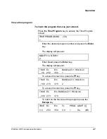
Page 10: ...ion Manager of Customer Service Phone 925 939 2400 or your local Varian Sales Service Center Unpacking WARNING Avoid back strain or injury by following all precautions for lifting heavy Carefully unpa...

Page 11: ...the instrument Use of a different power cable may result in an electric shock hazard This instrument is classified as 1 in IEC1010 1 Annex H and plug connected type in IEC1010 1 so connect the power...

Page 12: ...operation the detector should be located on a clean flat surface away from heat sources such as direct sunlight or a heater vent drafts such as an open doorway window or air conditioner vent corrosiv...

Page 13: ...roceed to the next section describing door installation Take the cap from the accessory kit and remove the protective paper exposing the adhesive that will attach the cap to the door Orient the door a...

Page 14: ...ssembly Installation and Removal of Door The module door may be attached to the front of the ProStar 363 to cover the tubing connections to the flow cell see Figure 5 Keep edge of door and door cap ev...

Page 15: ...nge pin into the top hinge Gently press down on the top of the door as shown in the figure and slide the lower hinge pin into the lower hinge and stop pressing The door should now pivot on the pins an...

Page 16: ...el Connect the power cord on the rear of the detector If the ProStar 363 will be controlled by the Star Workstation connect the serial cable 03 935462 01 to the serial connector on the back of the Pro...

Page 17: ...at each time point Stored spectral data Recorder Output Analog output for recorder 10 mV full scale The following signals can be output according to the setting Fluorescence intensity at each time poi...

Page 18: ...updated every 0 1 second The fluorescence intensity at the currently specified wavelength is output to the recorder The spectral data is output according to SPECT RCD setting of RECORD Hydraulic Conn...

Page 19: ...e removed from the terminator and the flow cell tubing can be connected directly Either the outlet tubing can be directed to the waste container or the tubing removed and the terminator itself dropped...

Page 20: ...14 03 914875 00 1...

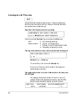
Page 21: ...luorescence time programmable detector controlled entirely from the local front panel keypad When the instrument is being controlled from the Star Workstation an L is displayed in the upper right hand...

Page 22: ...he exit slit After the exit slit the excitation light strikes the sample The fluorescence emitted light enters the emission monochromator where it is dispersed by the monochromator Monitor detector Ph...

Page 23: ...the intensity of the excitation beam as a function of time and corrects for changes in the lamp intensity Keyboard and Display All data entry is made via the keyboard on the front panel of the unit se...

Page 24: ...rum Obtains spectrum over a specified wavelength range and stores the spectrum in memory See Spect Param to specify scanning conditions Param Set Used to select the time constant pmt voltage emission...

Page 25: ...t of the instrument behind the door The flow cell provides a path for light to enter from the excitation monochromator and pass directly through to the monitor detector There is also a slit in the flo...

Page 26: ...enon Lamp Location The xenon lamp is mounted in a removable holder and adjusted with three screws located below at the bottom right of the lamp area These screws adjust the lamp in three dimensions up...

Page 27: ...lly performed when the instrument is powered up If the status display screen does not appear on the LCD within three minutes after turning on the power or if an error message appears on the LCD refer...

Page 28: ...ed when the detector is in the initial status R is indicated when it is in the time program running status B is indicated when it is in the busy status and L is indicated when it is in the key locked...

Page 29: ...pectral output can be performed at any time If spectral output is started during data acquisition the data is automatically directed to the integrator Normal Operation Selecting the Serial Communicati...

Page 30: ...t key The instrument parameters include TIME CONSTANT PMT VOLTAGE photomultiplier voltage Em BANDWIDTH emission bandwidth USE TIME PROGRAM selection of use non use of time program LAMP MODE selection...

Page 31: ...screen or press the key to go to the time constant screen Press the Escape key to return to the monitor screen without changing the current setting Specify an emission bandwidth Em BANDWIDTH STANDARD...

Page 32: ...creen Press the Escape key to return to the monitor screen without changing the current setting Selecting the Lamp Mode LAMP MODE OFF 0 ON 1 1 The currently specified lamp mode value is displayed on t...

Page 33: ...ength is acceptable simply press the key to go to the fluorescence wavelength screen or press the key to return to the monitor screen As an alternative press the Escape key to return to the monitor sc...

Page 34: ...TIME EX EM FL PROG LAMP I 0 0 250 350 xxxx x 1 Xe D1 To correct for baseline drift or if an adjustment to the zero setting is desired press the Auto Zero key to reset the output value to zero To Plac...

Page 35: ...100 steps can be included in the time programs e g one program can use 100 steps or 9 programs can use 11 steps etc TIME PROGRAM NO 1 9 1 The currently selected program number is displayed the default...

Page 36: ...fter the fluorescence wavelength is selected the cursor will appear in the BASE field Enter 1 to indicate if the Auto Zero feature should be used to reset the baseline or enter 2 to indicate if the pr...

Page 37: ...to 850 nm and 0 zero order c Fluorescence wavelength input range the default value is 350 nm The range of the fluorescence wavelength is from 250 to 900 nm and 0 zero order d Baseline processing inpu...

Page 38: ...he Utility Setup key The Utility screen provides access to the selection of a number of features including setting the signal offset value if the lamp should be automatically shut off when the program...

Page 39: ...n offset value OFFSET 0 1000 0 Numeric key ENTER key The currently specified value is displayed the default value is 0 The offset value adds a specified input signal value to the actual measured value...

Page 40: ...cified value is displayed the default value is 1 Input Value Meaning 1 FL mode Enter 1 for fluorescence intensity measurement Normal status screen 2 Ex M mode Enter 2 for excitation energy check 3 Em...

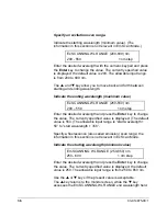
Page 41: ...n ranges maximum and minimum value press the Spect Param key The maximum wavelength scan range end wavelength start wavelength is 350 nm Select an acquisition scan mode SCAN MODE Ex 1 Em 2 2 Numeric k...

Page 42: ...550 1 nm step Enter the desired wavelength and press the Enter key to change the value The currently specified value is displayed The default value is 550 The allowable input range is start wavelength...

Page 43: ...maximum wavelength scan range end wavelength start wavelength for both excitation and emission is 350 nm For spectral acquisition in a range beyond 350 nm two separate scans will have to be made Colle...

Page 44: ...number and the current wavelength are displayed After the spectrum has been stored the status screen is presented The stored spectral data is not retained when power is turned OFF NOTE Stored spectra...

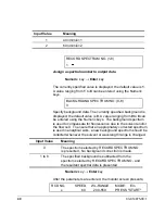
Page 45: ...corder speed Enter 2 to set recorder output speed 3 SPECT RCD Spectral recorder Enter 3 to set output data format RECORDER RANGE 1 1000 1000 Numeric key Enter key The recorder range only affects the r...

Page 46: ...ys The background spectrum is used to compensate for fluorescence due to the solvent and or the flow cell To ensure that an appropriately corrected spectrum is used in analytical work a new background...

Page 47: ...ing fluorescence due to solvent or impurities contained in the solvent and second order and third order emission will be superimposed on the fluorescence of the analyte Similarly an excitation spectru...

Page 48: ...ems b Check no longer used c Display of xenon lamp logbook data d Resetting of logbook function The key lock function can be used to deactivate the keypad KEY LOCK NO 0 YES 1 0 Numeric key Enter key T...

Page 49: ...Enter the appropriate data NOTE The logbook data entry is reset when the numeric value representing year and Enter are selected It is necessary to enter the year even if the lamp was last changed dur...

Page 50: ...be generated 1 At the start of the separation the Ex monochromator is set to 250 nm the Em monochromator is set to 350 nm and the autozero function is used to define the baseline 2 After 10 minutes th...

Page 51: ...display presents the operator with the opportunity to indicate if the present program should be modified or if a new program is to be entered If the MODIFY setting is selected the first line of the p...

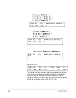
Page 52: ...Z 1 HOLD 2 1 00 2 70 370 2 2 0 key Enter key Escape key TIME Ex Em BASE A Z 1 HOLD 2 20 0 Monitor screen TIME Ex Em FL PROG LAMP I 0 0 250 350 0 0 1 Xe 90 To indicate that the program should be stoppe...

Page 53: ...he Enter key The display will present MODIFY 0 NEW 1 0 Enter 0 and press the Enter key The display will present TIME Ex Em BASE A Z 1 HOLD 2 _ 0 0 250 350 1 To access the next line press the key TIME...

Page 54: ...indicated in the Time 0 0 of the time program Shutting Down the Detector To turn the detector off turn off the Power switch The set measurement conditions are retained by the memory when the power is...

Page 55: ...Press the following keys Param Set key Enter key Enter key Enter key Enter key The following screen will appear LAMP MODE OFF 0 ON 1 1 On this screen press the 0 key followed by the Enter key to turn...

Page 56: ...bout 2 hours until it cools down sufficiently WARNING SHOCK HAZARD Potentially Dangerous Voltages are Present within the Instrument While the POWER switch is on a voltage of approximately 90V is appli...

Page 57: ...orbent cotton cloth moistened with high quality alcohol In this cleaning be careful not to apply strong impact or shock to the lamp Be sure to mount the lamp in the specified direction If the mounting...

Page 58: ...splay which indicates the date that the lamp was replaced the number of lamp starts and the period of time that the lamp has been on When the lamp installation date is changed the cumulative time and...

Page 59: ...lamp When the lamp goes on a high voltage of approximately 30 kV is applied to it To ensure safety however turn off the POWER switch and unplug the power cord from the outlet Before removing the xeno...

Page 60: ...of the lamp into the metal fixture on the ceramic plate Then using the anode nut mount the lamp so that the protruding part of the bulb is positioned as shown in Figure 14 Do not touch the quartz env...

Page 61: ...gerprints wipe it using the furnished cleaning paper or gauze absorbent cotton cloth moistened with high quality alcohol In this cleaning be careful not to apply strong impact or shock to the lamp Be...

Page 62: ...ument front panel side see Figure 14 Mount the xenon lamp so that the protruding part of bulb is positioned on the same side as the anode cord Anode cord Ceramic plate Metal fixture Anode nut Anode te...

Page 63: ...ulb NOTE Mount the xenon lamp so that the protruding part of the bulb comes to the instrument front panel side see Figure 14 A mistake in the positioning may cause an increased light loss and preclude...

Page 64: ...p clamp nut hold the metal parts on the anode and cathode sides with fingers Never hold the lamp bulb when securing it Take care not to apply excessive force or shock to the lamp bulb 4 After mounting...

Page 65: ...Figure 17 Connecting the Anode and Cathode Cables 6 After mounting the lamp holder reattach the light source cover Turn the power on and adjust the lamp as described in the following section Adjustin...

Page 66: ...the focal point of light source Adjustment of the lamp position involves a coarse adjustment in which the position of the light image is monitored and a fine adjustment in which the signal detected b...

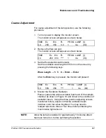
Page 67: ...the screen by pressing the following keys Wave Length 5 5 0 Enter Enter After the Enter key is pressed the monitor will present TIME Ex Em FL PROG LAMP I 0 0 550 350 1 Xe 90 4 Monitor the Excitation...

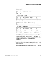
Page 68: ...Remount the flow cell unit The flow cell should be flushed with MeOH and blown dry with clean air 2 Change display mode Utility Setup 3 Display Mode Enter 2 Ex Enter Now the status display monitors Ex...

Page 69: ...the fine adjustment as described below Turn the FOCUS HORIZONTAL ADJ and VERTICAL ADJ screws gradually in a repetitive manner while observing the MONITOR value on the screen Turn each screw on an iter...

Page 70: ...d with an appropriate solvent Connect the syringe to the tip of drain tube and inject the washing solvent into the cell for cleaning If an aqueous mobile phase is used water should be used If an organ...

Page 71: ...scence Detector 65 Figure 20 Flow Cell Cleaning CAUTION If pressure is too high the flow cell may be damaged or broken When removing air bubbles set the pump pressure limit to 150 psi 10 atm or less F...

Page 72: ...leaning procedure disassemble the cell and clean its parts as instructed below Figure 21 Flow Cell Unit 1 Loosen setscrews A and detach the shielding plate 2 Detach the cell window 3 Loosen the upper...

Page 73: ...he ultrasonic cleaner to avoid scratching the cell 2 Wipe the surface of the flow cell with gauze moistened with acetone or ethanol CAUTION Be careful not to scratch the flow cell surface when disasse...

Page 74: ...the unit and make sure there is no leakage NOTE 1 During assembly be careful not to scratch the flow cell surface NOTE 2 Be sure you properly position the flow cell when putting it into the cell holde...

Page 75: ...d Ensure that the upper nipple is finger tight and then secure it using the wrench that is provided turn it through approximately 10 to 20 4 Remove all liquid on the outside of the flow cell and insid...

Page 76: ...hock Before replacing the fuse be sure to turn OFF the power switch and unplug the power cord from the outlet 1 Obtain a spare fuse 03 926131 12 Always use fuses of the correct rating and type 2 Make...

Page 77: ...ds to prevent burns The xenon lamp remains hot for a while even after power off and can severely burn you if touched Although the xenon lamp will be automatically extinguished by a safety mechanism wh...

Page 78: ...ey does not work On the monitor screen the data mode is not set to FL Check the monitor screen Using Utility Setup Mode setup Display Mode to FL 4 The Time Program does not start The instrument is not...

Page 79: ...ed compound is eluting from the column Stop feeding liquid from the pump Wait until elution is completed or replace the column with a new one There is a significant change in the ambient temperature C...

Page 80: ...RIVE MECHANISM ERROR The monochromator cannot properly set during the self diagnosis test initialization Turn power on again Notify the nearest Varian service center ROM ERROR Error in ROM Notify the...

Page 81: ...n differs from spectrum slit position Select correct parameters PARAMETER ERROR Error in parameter data data cannot be retained due to EEPROM error Turn on power again Contact your nearest Varian serv...

Page 82: ...76 03 914875 00 1...

Page 83: ...er than 731 nm Excitation side spectral bandwidth 15 nm Emission side spectral bandwidth 15 or 30 nm Wavelength setting By keyboard or through Star Workstation Wavelength accuracy 3 nm Wavelength repe...

Page 84: ...wavelength emission wavelength baseline processing Display function 40 characters 2 lines on backlighted LCD Communication function RS 422 485 serial communication External output terminals Analog ou...

Page 85: ...e 0 33 ID outlet Length 2 m Outside diameter 1 57 mm 03 926131 19 Nitoflon tube 0 25 ID inlet Length 2 m Outside diameter 1 57 mm 03 926131 11 Standard photomultiplier R3788 56 180002 00 Extended rang...

Page 86: ...es not contain any compound that fluoresces If there is any doubt whether an observed peak is a Raman peak a Rayleigh peak or a peak due to the fluorescence from the compound of interest simply change...

Page 87: ...Wavelength Excitation Wavelength Water Ethanol Cyclohexane Carbon Tetrachloride Chloroform Excitation wavelength and Raman peak position nm 248 271 267 267 313 350 344 344 320 346 365 416 405 408 375...

Page 88: ...not excited by the incoming radiation since it was already absorbed The example described above is an extreme situation Typically if the absorbance of the sample is greater than 0 05 the inner filter...

Page 89: ...set to transmit radiation of a specific wavelength e g 250 nm will also transmit multiples of the radiation e g 500 nm When a fluorescence spectrum is collected the analyst should be aware of the seco...

Page 90: ...interest and the second order radiation is rarely a problem Typically the peak for the compound of interest might correspond to peak 3 and the analyst might have to correct for the Raman peak e g use...

Reviews: