


BDR-595 E EuroAdela
20
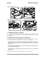
2. Hold the upper disk so that it does not turn and dismount the knife bolted connection by
using the barrel spanner No. 16 and flat wrench No. 17.
3. Take the knife and parts of knife seating out of the mowing disk. Level the blade and
sharpen the knife cutting edges. Inclination of the sharpened blade should be 30° with
respect to the lower plane of the knife.
,
Should some of knives be bent or showing a considerable wear, you must always
replace all knives in the mowing disk!
4. Screw back the bolt with the filler, knife and flat washer. Than screw on the nut.
5. Hold the bolt head with the barrel spanner No. 16 and tighten the nut. All knives must
freely rotate on the bolts. The knives have blades on both sides; when one side is worn
out, the knife can be reversed and the blade of the other side can be used. When replacing
the knife, replace also all damaged parts of the knife clamping (see Fig. 6).
Note: Manufacturer does not answer for damages caused by the machine if the knives
were repaired by unskilled persons without the use of the original spare parts. There is a
“VARI“ stamp on the knife, which identifies the manufacturer and is at the same time a
control mark indicating that the knife is an original spare part.
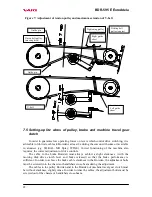
7.4 V-belt replacement and adjustment of tightening pulley
The V-belt should be replaced according to its wear (cracked sides, torn belt, sides worn
out down to belt carrier fibres, belt pulled out of shape) or after about 100 hours of operation
at the maximum. In this machine, the belt stretched to maximum is considered a belt in which
the distance between the internal belt surfaces is lesser than 7 mm (with the pressed lever of
mowing disk drive clutch) – see Fig. 7.
The replacement procedure is as follows:
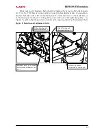
Nut M10
Order no.189 561
Washer
Order no. 189 587
Knife
Order no. 189 060
Washer 10.5
Order no. 131 518
Bolt M10x30
Order no. 189 545
Figure 6: Knife clamping on the mowing disk
Summary of Contents for BDR-595 E EuroAdela
Page 1: ...Drum mower BDR 595 E EuroAdela Instructions for use...
Page 8: ...BDR 595 E EuroAdela 8 LwA 2 1 3 4 5 6 7 8 11 12 9 10...
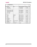
Page 28: ...BDR 595 E EuroAdela 28 8 List of components...
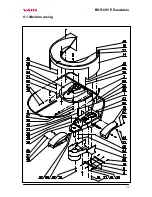
Page 29: ...BDR 595 E EuroAdela 29 8 1 Machine casing...
Page 31: ...BDR 595 E EuroAdela 31 8 2 Handlebars...
Page 33: ...BDR 595 E EuroAdela 33 8 3 Mowing disk drive...
Page 35: ...BDR 595 E EuroAdela 35...
Page 36: ...BDR 595 E EuroAdela 36 8 4 Wheel driving gear...