background image


23 

Pos. 

Part No. 

Name 

Pcs 


Pos.  Part No. 

Name 

Pcs 

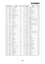
76 

211076 

Screw M4x60 


97 

211097 

O-ring 50x2,65 

77 

211077 

Switch 


98 

211098 

Oil filter K 

78 

211078 

Locknut M4 


99 

211099 

Bush K 

79 

211079A 

Motor 11 ton 


100 

211100 

Flange 

79 

211079B 

Motor 14 ton 


101 

211101 

Locating plate 

80 

211080A 

Gear pump 11 ton 


102 

211102 

Hook 

80 

211080B 

Gear pump 14 ton 


103 

211103 

Rectangular nozzle 

81 

211081 

Screw M8x90 


104 

211104 

Locknut M14 

82 

211082 

Oil hose 16 


105 

211105 

Torsional spring 

83 

211083 

Hose clamp 20-26 


106 

211106 

Locating bush for spring 

84 

211084 

Wheel cap 


107 

211107 

Locating bush 

85 

211085 

Wheel 


108 

211108 

Bolt M14x60 

86 

211086 

Flat washer 16 


109 

211109 

Large washer 14 

87 

211087 

Cotter pin 2x20 


110 

211110 

Screw M6x10 

88 

211088 

Wheel axle 


111 

211111 

Handle grip 

89 

211089 

Locknut M16 


112 

211112 

Support wheel assy. 

90 

211090 

Bolt M16x90 


113 

211113 

Bolt M10x25 

91 

211091 

Screw plug 


114 

211114 

Fixing tube 

92 

211092 

Combined washer 22 


115 

211115 

Pin B 16x85 

93 

211093 

Main frame 


116 

211116 

Clip 3 

94 

211094 

Bolt M6x12 


117 

211117A 

Pin B 12x50 (11 ton) 

95 

211095 

Flat washer 6 


117 

211117B 

Pin B 12x55 (14 ton) 

96 

211096 

Buffer spring 


DISPOSAL OF PACKAGING AND MACHINE AFTER THE 
END OF SERVICE LIFE 

 
After unpacking the machine, you are obliged to provide for the disposal of packaging 
material with taking into account the use of secondary raw materials according to the 
legislation valid in your country and with respect to the decrees of local town or 
municipal authorities. 
The following procedure is recommended for machine disposal after the end of its 
service life: 

1. 

Dismount all parts from the machine that can still be used. 

2. 

Dismount plastic machine parts and parts made of non-ferrous metals. The 
dismantled machine remainder and the dismounted parts are to be disposed 
according to the legislation valid in your country and with respect to the 
decrees of local town or municipal authorities. 

3. 

Regarding waste from the electrical device, use the opportunity of 

return buy-

out

 in the shop, where you purchased the device 

(points 1 and 2 are not 

valid in this case)

4. 

The machine is in accordance with the RoHS Directive 
(2002/95/EC, 2002/96/EC, 2003/108/EC). 


Summary of Contents for 65710

Page 1: ...N SUPER FORCE VARI 14 TON SUPER FORCE SERIAL NUMBER Both model number and serial number may be found on the main label You should record both of them in a safe place for future use Save This Manual fo...

Page 2: ...oduce technical modifications and innovations which do not affect the function and safety of the machine These modifications may not necessarily be specified in this user manual Printing errors reserv...

Page 3: ...tions in full before using the machine Wear safety footwear Wear protective gloves Wear eye protection Wear hearing protection Keep your work space tidy Untidiness may result in accidents Do not remov...

Page 4: ...ood when machine is leaning SAFETY SAFETY WARNINGS INSTRUCTIONS UNDERSTAND YOUR LOG SPLITTER Read and understand the owner s manual and labels affixed to the log splitter Learn its application and lim...

Page 5: ...wet muddy or icy surfaces The location you choose should be free from any tall grass brush or other interferences There should be plenty of room for handling and help the operator stay alert Keep your...

Page 6: ...tipped or if the cutting tool is unintentionally contacted Do not store anything above or near the log splitter where anyone might stand on the tool to reach it AVOID INJURY FROM UNEXPECTED ACCIDENT...

Page 7: ...not qualified to use it DEAL WITH ACCIDENT Always have a fire extinguisher and a first aid kit available for use should the need arise In emergency always know the location of the nearest phone or ke...

Page 8: ...ONDITIONS This log splitter is designed for operating under ambient temperatures between 5 C and 40 C and for installation at altitudes not more than 1000 m above M S L The surrounding humidity should...

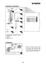
Page 9: ...lift 4 Retaining hook 5 Wheel 6 Wheel axle 7 Support wheel 8 Operator s manual 9 Hardware bag including ASSEMBLY 1 Insert the wheel axle into the holes of the mount bracket Slide the wheels onto the...

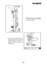
Page 10: ...2 Keeping the support stand against the wedge remove the R Pin and bolt to release cylinder Lower both control handles to raise the wedge ram to the top Insert the bolt and R pin to secure the cylind...

Page 11: ...trol handles to retract the wedge ram Remove the support stand 4 Align the hole and locking pin of the guard arm with the mount bracket Secure the guard arm with an M10x30 hex bolt a washer and a nut...

Page 12: ...onto the frame and secure with two M10x30 hex bolts and nuts 6 Position the log lift inside the mounting bracket and align with mounting bracket holes Secure with an M16x90 hex bolt and nut Hook the...

Page 13: ...or transport and lower hole is only for storage Because the support wheel is a universal wheel it is not stable enough for transport if mounted at the lower hole The transporting handle is fixed uprig...

Page 14: ...ition the log splitter on solid level ground Applying a thin coat of grease to the surfaces of the ram before operation will lengthen the durability of the ram Bleed the air out of the hydraulic syste...

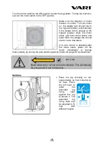
Page 15: ...wedge ram should start to move downward If no ram motion is detected after the motor starts power off the motor immediately to change motor polarity by turning the pole switching device inside the pl...

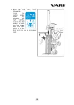
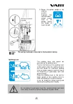
Page 16: ...the left press lever Meanwhile move the splitter wedge down by pressing the right splitting lever to the half stroke to split the log slowly first and then press it to the end until the log is complet...

Page 17: ...he splitting lever is idle speed press the splitting lever to the half stroke for maximum splitting force at slower speed to split the log at the beginning or particularly hard and seasoned logs Press...

Page 18: ...rk environment Never continue to work in a cluttered work area which may cause you to slip trip or fall FREE A JAMMED LOG Do not remove jammed logs with your hands If jammed stop the motor and loosen...

Page 19: ...Read dipstick to determine the maximum and minimum of the oil level Low oil can damage the oil pump Overfilling can result in excessive temperature in the hydraulic transmission system Apply sealant t...

Page 20: ...er does not work while motor running Valve is not opened owing to the connection parts loosening Check and tighten the parts Control Levers or connection parts bent Repair the bent parts Lower hydraul...

Page 21: ...21 PART LIST...
Page 22: ...ght plate 1 53 211053 Handle grip 1 17 211017 Nut M12 6 54 211054 Square plug 1 18 211018 Axis pin 1 55 211055 Pull rod 1 19 211019 Cap 12 2 56 211056A Connecting plate for valve 11 t 1 20 211020 Lift...

Page 23: ...16x85 1 93 211093 Main frame 1 116 211116 Clip 3 3 94 211094 Bolt M6x12 4 117 211117A Pin B 12x50 11 ton 2 95 211095 Flat washer 6 4 117 211117B Pin B 12x55 14 ton 2 96 211096 Buffer spring 1 DISPOSAL...

Page 24: ...ne number fax number or e mail address 5 Should you be uncertain about the correct identification of the component send the damaged component either to the nearest service shop or directly to the manu...

Page 25: ...25 EC DECLARATION OF CONFORMITY1 1 The original declaration of conformity as issued by the manufacturer of the product...

Reviews: