6
1.3
Plumbing Considerations
1.3.1
Cold water supply
General
The Vapanet range of electrode boilers is capable of
operating with a range of “raw mains” water quality. The
water supply should be within the following limits:-
Hardness 50 – 500 ppm
Conductivity 80 – 1000 µS*
PH 7.3 – 8.0
Silica
0
Pressure of between 1.5 - 8 bar.
Chlorine <170 ppm
Water Supply rates
0.25 l/min
LFE05
Do’s
Do
install a stop-valve/Shut-off valve and a strainer close to
the unit.
Do
provide a water supply with sufficient pressure and pipe
size to ensure an adequate flow rate to all units connected
to the system.
Do
use the flexible hose connection with nylon nut provided.
Don'ts
Don’t
use a wrench or other tool to tighten the water supply
connection - the nylon nut and rubber washer provided,
should only require tightening by hand to effect a seal. If
water seepage occurs, undo the nut to wipe the washer clean
and re-seat it.
1.3.2
Drain connection
General
Do's
Do
ensure metal drain and supply water pipework is
grounded electrically close to the unit (a ground/earth stud
is positioned on the underside of the cabinet).
Drain capacity per cylinder and drain tray pump
= pump discharge rate of max 11.8 l/min at 50 Hz.
Power supply 12.2 l/min at 60 Hz.
Do’s
Do
use copper or plastic pipe rated for 110
o
C.
Do
arrange to discharge drain water from the unit into a
trapped and vented drain at a position where flash steam
rising from the drain line vent will not pose a problem for
the Vapac or other equipment.
Do
provide adequate fall for the drain pipe work to allow free
flow of water drained from each unit.
Do
ensure drain line pipe size will accommodate water being
drained at the same time from all the Vapac units which
are connected to it.
Do
ensure drain line has a min full of 5° 1 in 12 pipe (8%) fall
and sized adequately to take all units connected into it at
fall pump flow rate each LFE unit has two pumps one from
drain tray the other from cylinder both have the same flow
rate as above.
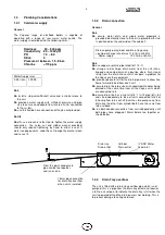
Do
run both condensate outlets from unit independently until
both pipes have dropped 100mm before tee together as
shown below.
1.3.3
Drain Tray overflow
The unit is fitted with a drain tray overflow pipe which is not
pumped, this is a pipe from the drain tray direct and requires
a fall to a visual point to indicate the drain tray is full when the
unit is powered off and the drain pump is not working. This is
to prevent damage to ceiling void area.
Drain tray
Cylinder
¾” BSP Water
Drain outlet
Drain outlet
Feed inlet
From this point condensate
pipe can be tee together
and run as one.
15mm pipe connection
for drain tray overflow
when unit is isolated.
Summary of Contents for VapaNet LFE Series
Page 19: ...19 3 3 Facia Label symbols 1 ...
Page 21: ...21 ...


