


www.fmiproducts.com
125784-01D
18
INSTALLATION
Continued
Configuration
Change
Back
Yes
No
0.5°C
Thermostat
Programming
Gap Temp
Fri 22:05
Off
Pairing
Configuration
Select Back
Off
No
Yes
0.5°C
Thermostat
Programming
Gap Temp
Fri 22:05
Pairing
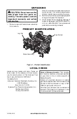
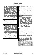
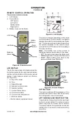
Figure 24 - Change OFF to ON
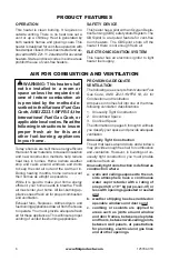
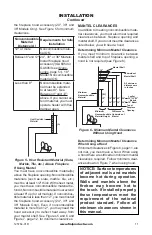
Figure 25 - Signal Bars
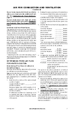
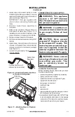
Figure 26 - Back and Middle Buttons
Configuration
Change
Back
Yes
No
0.5°C
Thermostat
Programming
Gap Temp
Fri 22:04
On
Pairing
Change
Button
Configuration
Change
Back
Yes
No
0.5°C
Thermostat
Programming
Gap Temp
Fri 22:05
Off
Pairing
Configuration
Select Back
Off
No
Yes
0.5°C
Thermostat
Programming
Gap Temp
Fri 22:05
Pairing
Back
Button
Middle
Button
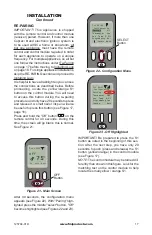
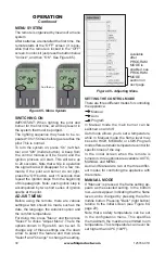
Press the left "Change" button and "Off" becomes
"On" (see Figure 24, above). Press the S1 but
-
ton to re-pair the remote to the control module.
Once this operation is done, you will hear one
beep in the control module and the configura
-
tion menu will show signal bars:
(see
Figure 25). If you do not hear the beep and then
see signal bars within 30 seconds of hearing
the beep, then the repairing process was not
completed successfully. If this occurs, remove
the batteries from the remote control, wait 3
minutes, and restart the re-pairing process. If
you see signal bars, then the remote control
has paired properly. Go to the next step.
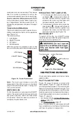
Press the “Back” button once to return the
highlighted selection to “Pairing”. Press the
“Middle” button and release. The indication on
the “Pairing” will become “Off” (see Figure 26).
The re-pairing is over. To return to the main
screen, press the “Back” button until you get
to the main screen. The main screen is shown
in Figure 21, page 17.
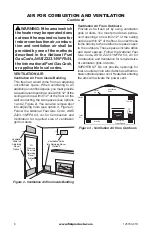
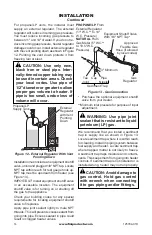
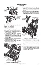
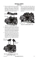
INSTALLING LOGS
WARNING: Failure to position
the parts in accordance with these
diagrams or failure to use only
parts specifically approved with
this heater may result in property
damage or personal injury.
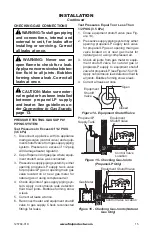
Log Support Brackets
If installing a LBG36-SM, attach log support
brackets before installing logs. These brack-
ets are provided with the BGE2436 series
burner systems.
1. Install left bracket to left side of chassis using
2 screws provided (see Figure 28, page 19).
2. Install right bracket to right front of chassis
using 2 screws provided (see Figure 28,
page 19). This bracket will also be used as
remote control bracket if remote is installed.
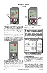
BG & BGE Series Burner System - Log
Compatibility Chart
Burner System
Models
Fiber Log
Models
Concrete Log
Models
BGE18NE
BGE18PE
LBG18-SM
LBG18-CM
LBG18-RM
LBG18-BM
BGE2436NE
BGE2436PE
LBG24-SM
LBG30-SM
LBG36-SM
LBG24-CM
LBG30-CM
LBG24-RM
LBG30-RM
LBG24-BM
LBG30-BM
Figure 27 - BG & BGE Series Burner
System- Log Compatibility Chart


