background image

Programming 

24 

Vanderbilt International (IRL) Ltd.


05.2016 


6.3.3 

List of the Installer Programming Modes 


Parameter 

Value 

Description 

C1 and C2 

00–99 

The C1 and C2 digits define time for which the reader activates the door 
lock when access is granted. The C1C2 digits are called 

Door Lock Trig-

gering Time,

 the C1C2 time is defined in seconds.  

Note: When set to C1C2=00, each time the reader grants access the 

Door Lock Output

 is turned to the opposite condition (toggle mode). Also 

the C1C2=00 setting disables the 

Door Ajar

 alarm (Door Held). 

C3 and C4 

00–99 

The C3 and C4 digits define 

Time Allowed to Close the Door

 (in sec-

onds). If during this time the door is not closed the Door Ajar alarm (Door 
Held) will arise. The C3C4 timer is started immediately after the Door Lock 
Triggering Time (C1C2) has elapsed. 

C5 

0 – 7 

Function settings for the REL1 output on the ACS6311 module or for the 
reader’s CLOCK line (depending on actual reader Operating Mode se-
lected): 

[0] - 

Not Used

, line ignored; 

[1] – 

Door Contact Input

, the line shorted to the power supply minus indi-

cates that the door is closed; 

[2] – 

Exit Button Input

, each time the line is shorted to the power supply 

minus the reader grants access; 

[3] – 

Arming Disabled Input

, when the line is shorted to the power supply 

minus, the reader can not be armed.  

[4] – 

Door Lock Output

, used to activate the door releasing device (an 

electric lock or an electric strike); 

[5] – 

Reader Disarmed Output

, the line is active when the reader oper-

ates in DISARMED Mode; 

[6] – 

Door Alarm Output

, the line is active when the reader has detected 

any alarm situation, the output is modulated according to the detected 
alarm type. If more then one alarm has been triggered, the output signals 
is the one of the highest priority; 

C6 

0 – 7 

Function settings for the REL2 output on the ACS6311 module or for the 
reader’s DATA line - assignments as for C5. 
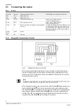
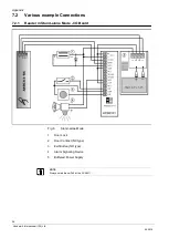
C7 

0 – 3 

e.g. value=1 

door contact input 

(yellow lead connected to  
minus = door closed) 

Function settings for the reader’s IN1 line: 

[0] – 

Not Used


[1] – 

Door Contact Input


[2] – 

Exit Button Input


[3] – 

Arming inhibition 


C8 

0 – 3 

Function settings for the IN1 line on the ACS6311 module – assignments 
as for C7. 

C9 

0 – 3 

Function settings for the IN2 line on the ACS6311 module – assignments 
as for C7.


C10 

0 – 1 

Internal use 

C11 

0 – 1 

Internal use 


NOTE 

If the „door feedback contact“ and the „door alarm output“ are activated and the door is forced open, 
the card reader will produce an audible alarm signal. In order to deactivate the buzzer on the reader 
after a door alarm, the door must be closed and opened again using a valid card. 


Summary of Contents for ARS6311-RX

Page 1: ...Vanderbilt International IRL Ltd Card reader ARS6311 RX Configuration Manual...

Page 2: ...ne unsere vorg ngige schriftliche Erm chtigung ganz oder teilweise Dritten zug nglich machen oder au erhalb des Zweckes verwenden zu dem es ihm bergeben worden ist We reserve all rights in this docume...

Page 3: ...3 Connecting the reader 16 5 3 1 Ports 16 5 3 2 Wiegand Transmission Format 16 5 3 3 Magstripe Transmission Format 17 5 3 4 Address setting 17 6 Programming 18 6 1 Setting Reader Operation Mode 19 6 1...

Page 4: ...4 Vanderbilt International IRL Ltd 05 2016...

Page 5: ...for unsuitably or incorrectly set parameters whether automatic or manual or for inappropriate use of the unit All repairs must be carried out by the manufacturer The user is responsible for ensuring...

Page 6: ...protection IP 65 Dimensions 100 x 40 x 25 mm Cable length 400 mm Weight Approx 110 g Approvals CE I O Board ACS6311 Input voltage 10 16 V DC Current consumption 100 mA both relays activated Inputs Two...

Page 7: ...ata transmission formats available for use in ONLINE Mode which include the popular Wiegand and Magstripe i e simulation of output of a magnetic card reader data protocols When configured for Stand al...

Page 8: ...Support for Door Contact DC and Request To Exit REX push button Door Alarm and Door Bell outputs Integration to intrusion alarm system through I O s Entry Exit control requires two ARS6311 RX to form...

Page 9: ...user to whom the programmed card will belong as a result the reader simply stores the programmed card with the unoccupied user ID number The full programming procedure requires you to specify an ID nu...

Page 10: ...fter Memory Reset the reader always enters ARMED Mode 4 4 3 Arming and Disarming of the Reader re arming Changing the reader s state from ARMED to DISARMED and back is called re arming in this manual...

Page 11: ...ring Time The lock acti vation is signaled on LED OPEN green which remains on for as long as the door lock is energized When access to the supervised room is denied the reader generates a long beep Th...

Page 12: ...the door is closed If more than one alarm is triggered the reader indicates the alarm with the highest priority The Forced Entry and the Door Ajar alarms Door Held will occur only if the reader opera...

Page 13: ...Legend one long audible signal one short audible signal beep LED Indications in Stand alone Operation Mode LED STATUS LED OPEN LED SYSTEM Description Green The reader is in DISARMED State Red The rea...

Page 14: ...g separate power supply sources connect all power supply negative leads together We recommend to ground the negative power supply lead With its relatively weak electromagnetic field generation the ter...

Page 15: ...Installation 15 Vanderbilt International IRL Ltd 05 2016 5 1 Opening the housing Fig 1 Opening the housing 5 2 Mounting Fig 2 Mounting direction...

Page 16: ...t used 5 3 2 Wiegand Transmission Format Fig 3 Wiegand Transmission Format When employing Wiegand transmission format the data is transferred using se quences of pulses sent over the CLOCK and DATA li...

Page 17: ...indicators and the buzzer are controlled in the same manner as described for Wiegand for mats see previous section In Magstripe format the ARS6311 RX send the serial number of the card The default se...

Page 18: ...using the adequate Programming Card use your Master Card when in User Programming Mode or use your Installer Card when in Installer Programming Mode The AR6311 RX can be programmed by multiple reading...

Page 19: ...slave reader connected to master ARS6311 RX Use this mode for two way door control systems 04 OFFLINE Mode Stand alone Mode The reader operates as a Stand alone Unit its CLOCK and DATA lines are used...

Page 20: ...mple Configuring the ARS6311 RX for Offline Mode Stand alone Mode Code 04 1 Power down the unit 2 Remove all connections from DATA bn and IN1 lines ye 3 Connect DATA bn to IN1 ye 4 Restore power the r...

Page 21: ...IN1 ye 7 Present any card to the reader this card becomes a new Master Card 8 Present any other card to the reader this card becomes a new Installer Card 9 Once the previous step has been completed th...

Page 22: ...6 3 1 Configuration Default settings Configuring the reader for the following set of installer s options Start programming using the installer card Enter the values for the parameters C1 to C11 succes...

Page 23: ...r Card 1 time to the reader program C3 1 Wait for the acoustic prompt 5 Present your Installer Card 1 time to the reader program C4 1 Wait for the acoustic prompt 6 Present your Installer Card 4 times...

Page 24: ...s access 3 Arming Disabled Input when the line is shorted to the power supply minus the reader can not be armed 4 Door Lock Output used to activate the door releasing device an electric lock or an ele...

Page 25: ...A new user is registered in the terminal s memory at the location cor responding to his specified ID number he is assigned the proximity card presented in the last step of the command Add one Normal...

Page 26: ...r has registered the new user card in its memory and exited the pro gramming function however it has not left User Programming Mode so that now you may use your next desired programming command or you...

Page 27: ...27 Vanderbilt International IRL Ltd 05 2016 7 Appendix 7 1 Dimensions Fig 5 Dimensions 1 Tamper 2 Electronic circuit board fully potted 3 Cable length 400 mm LED STATUS ARMED DISARMED Mode LED OPEN LE...

Page 28: ...16 7 2 Various example Connections 7 2 1 Reader in Stand alone Mode I O Board Fig 6 Stand alone Mode 1 Door Lock 2 Door Contact NC type 3 Exit Button NO type 4 Alarm Signaling Device 5 Buffered Power...

Page 29: ...t or the local authorities This crossed out wheeled bin symbol on the product means the product is covered by the European Directive 2002 96 EC The correct disposal and separate collection of your old...

Page 30: ...Appendix 30 Vanderbilt International IRL Ltd 05 2016 7 5 List of Users Site name Reader location ID number Card number Type User name Master Installer...

Page 31: ...Appendix 31 Vanderbilt International IRL Ltd 05 2016 List of Users Site name Reader location ID number Card number Type User name...

Page 32: ...ness and Technology Park Clonshaugh Dublin 17 Ireland www vanderbiltindustries com 2015 Copyright by Vanderbilt International IRL Ltd Data and design subject to change without notice Supply subject to...

Reviews: