


Installation
16
Vanderbilt International (IRL) Ltd.
05.2016
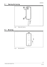
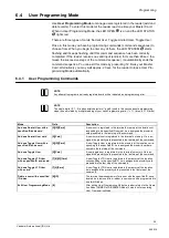
5.3
Connecting the reader
5.3.1
Ports
Wire Color
Function
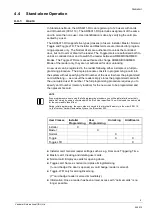
Stand-alone Operation Mode
ONLINE Mode (unit connected to host ACU)
Red
+12 V
Supply input plus
Blue
GND
Supply input minus
Green
CLOCK
CLOCK communication line
DATA 0 line for Wiegand formats
CLOCK for Magstripe format
Brown
DATA
DATA communication line
DATA 1 line for Wiegand formats
DATA for Magstripe format
Yellow
IN1
Electric input (can be configured to several available
functions).
In Wiegand and Magstripe formats (LED green), the
IN1 line activated by shorting it with the supply mi-
nus (GND). When IN1 is triggered it turns the LED
OPEN to ON and also activates acoustic signal on
the Internal Buzzer.
Grey &
White
TAMP
Tamper
Pink
NC
Not used
5.3.2
Wiegand Transmission Format
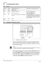
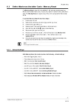
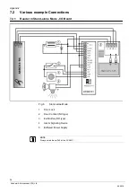
Fig. 3
Wiegand Transmission Format
When employing Wiegand transmission format, the data is transferred using se-
quences of pulses sent over the CLOCK and DATA lines. Depending on the se-
lected version of the transmission format, the ARS6311-RX uses 26, 34 or 42 bits
to transmit a data to a host.
NOTE
For card code length longer than the number of bits available in the selected data transmission format
a ARS6311-RX reader omits the most significant bits of the data transmitted.
When Wiegand format is used, the dual color LED STATUS
lights steady in red
and the LED SYSTEM
turns on for a short while with each reading of a card.
The LED OPEN
is controlled by the IN1 input line. When IN1 is shorted with the
power supply negative lead the LED OPEN
turns on and the Internal Buzzer
sounds, when IN1 is shorted with the power supply positive terminal or is left un-
connected the LED OPEN
and the Buzzer is not active.


