www.vanco1.com
800.626.6445
5
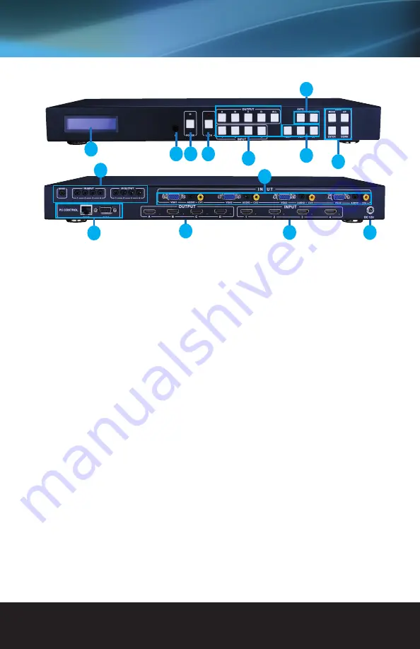
1. LCM: Displays the information of each input and output setting and EDID management.
2. IR: IR Receiver window (accepts the remote control signal of this device only).
3. POWER: Press this button to power the device on/off. The LED will illuminate green when the power is on,
red when it is in ‘Standby’ mode.
4. LOCK: Press this button to lock all the buttons on the panel, press again to unlock.
5. OUTPUT/INPUT: Press the OUTPUT and INPUT button to select the output corresponding input.For
example: Press OUPUT ALL>INPUT 1,The OUTPUT A,B,C,D will be set to INPUT 1.
6. Picture adjust:Press the button to adjust the output picture. For example:Press output 1>SCALER, The
output 1 video will be scaler adjust. Note: 1. AUTO ADJUST button only work on VGA input.
7. Sources input select: Press the button to select source input. For example:Press input 1>VGA,The input 1
will be select the VGA video input.
8. EDID: Smart EDID management, the LCM will display the EDID operation. Press the MENU button to
enter the EDID management window, press UP or DOWN button to select the needed EDID setting, press
ENTER button to select the download input source. It can easy download any EDID mode to any input
source.
9. IR Channel: IR EXT: if the panel sensor is obstructed or the unit is installed in a closed area out of infrared
line of sight, a provided IR RX receiver can be inserted into the IR EXT port at the rear to extend the IR
sensor range and enable local control of the matrix. IR IN: When used with the provided IR RX receivers
will receive and send IR from a remote location for control purposes. IR OUT: When used with the
provided IR TX emitters will discreetly control the sources/inputs when selected in a specific zone.
10. VGA CV AND AUDIO INPUT: Connect to the VGA or CV input source device such as a DVD player, a Set-
top Box or PC with VGA cable or RCA cable. Each VGA or CV input is accompanied with a 3.5mm stereo
audio input.
11. PC CONTROL: TCP/IP: This port is the link for TCP/IP controls, connect to an active Ethernet link with
an RJ45 terminated cable. RS232: Connect to a PC or control system with D-Sub 9pin cable for the
transmission of RS-232 commands.
12. OUTPUT:The HDMI OUTPUT connect to HDMI equipped TVs.
13. HDMI INPUT:Connect to the HDMI input source devices such as a DVD player or a Set-top Box with HDMI
cable.
14. DC POWER INPUT: Plug the 12V/2.5A DC power supply into the DC12V power in.
PANEL DESCRIPTIONS
7
8
12
13
14
1
2 3 4
5
6
9
10
11


