Vanair AIR N ARC RELIANT 300 Series Operations Manual & Parts List Download Page 160

SECTION 9: ILLUSTRATED PARTS LIST

AIR N ARC

®

 300 SERIES ALL-IN-ONE POWER SYSTEM

®

PAGE - 142

090034-OP_r0

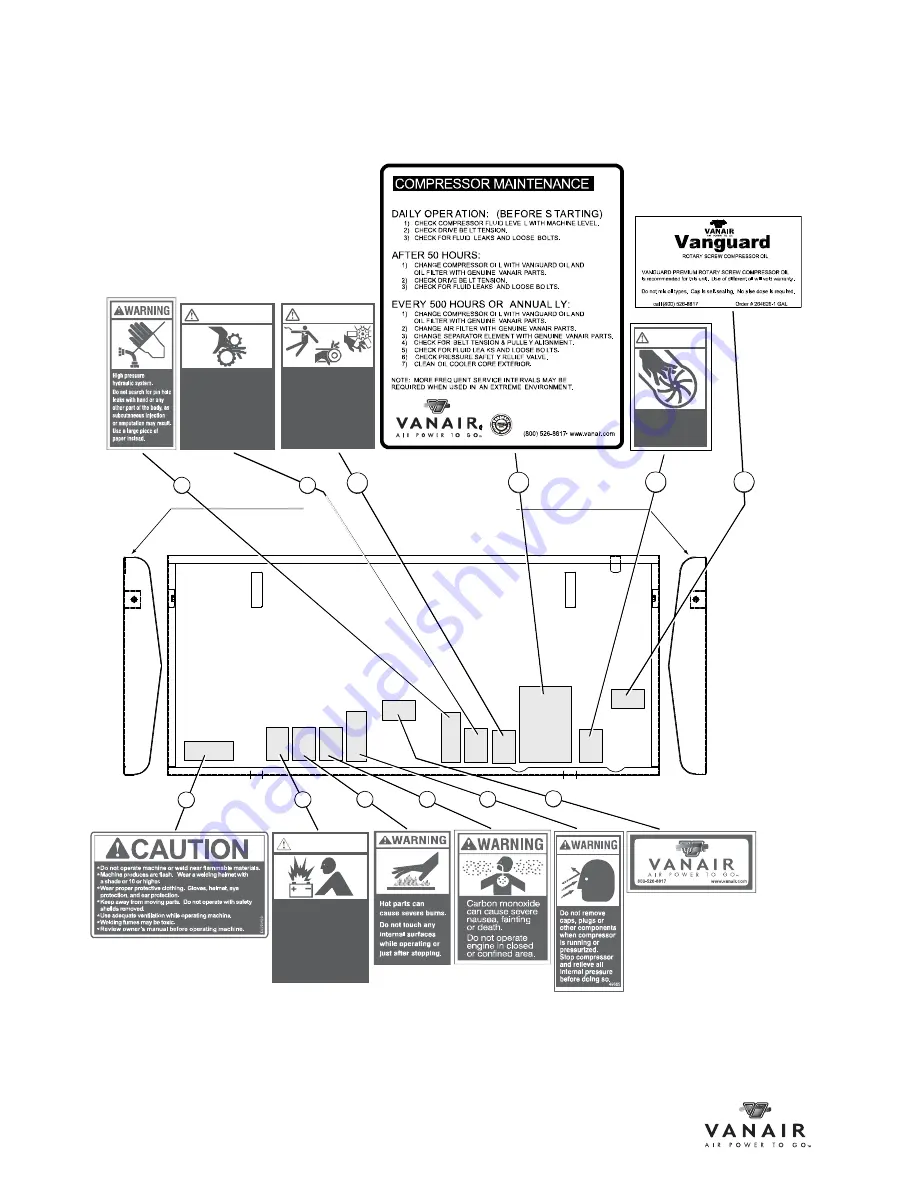
9.12 DECAL LOCATIONS (1 OF 3) 

Inside view of hood panel ends

Inside view of hood panel

WARNING

Sulphuric acid in

batteries can cause
severe injury or death.
Change only in

well-ventilated area.
Keep sources of

ignition awa y.

Rotating parts

can cause

severe injury.
Stay away while

engine and

compressor are

in operation.

WARNING

Accidental starts

can cause severe

injury or death.
Disconnect battery

and ground

spark plug lead

before servicing.

WARNING

Do not operate
without fan guard
in place.

WARNING

1

2

3

4

5

9

10

11

6

7

8

12

Summary of Contents for AIR N ARC RELIANT 300 Series

Page 1: ...king unauthorized modifications to the system components WILL VOID THE WARRANTY Always inform Vanair Manufacturing Inc before beginning any changes to the Air N Arc system NOTE Use only Vanair Vanguar...

Page 2: ...cial industrial users and persons trained and experienced in the use and maintenance of industrial equipment In the event of a warranty claim covered by this Limited Warranty the exclusive remedies sh...

Page 3: ...NOTE ON MANUAL LAYOUT NAVIGATION 1 SECTION 1 SAFETY 3 1 1 GENERAL INFORMATION 3 1 2 DANGERS WARNINGS CAUTIONS AND NOTES 3 1 3 INTERNATIONAL SAFETY SYMBOL 4 1 4 ARC WELDING HAZARDS 4 1 4 1 ELECTRICAL...

Page 4: ...TTING AND GOUGING CAN CAUSE FIRE OR EXPLOSION 12 1 6 6 HOT PARTS CAN CAUSE SEVERE BURNS 12 1 6 7 READ INSTRUCTIONS 13 1 7 ADDITIONAL SYMBOLS FOR INSTALLATION OPERATION AND MAINTENANCE 13 1 7 1 FALLING...

Page 5: ...2 4 MOTOR 26 2 5 AC GENERATOR 26 2 6 INSTRUMENTATION 27 2 6 1 VOLTS AMPS METER 28 2 6 2 WELDER FUNCTION SWITCHES 28 2 6 3 DC CHARGER MODE TOGGLE SWITCH 28 2 6 4 VOLTS AMPS MANUAL ADJUSTMENT DIAL 28 2...

Page 6: ...L OVERVIEW OF INSTALLATION 38 4 4 PREPARING THE VEHICLE SERVICE BODY 38 4 4 1 MACHINE CLEARANCE ALLOWANCE 40 4 4 2 DETERMINING PROPER VENTILATION REQUIREMENTS 40 4 4 3 ROOF REQUIREMENTS IF APPLICABLE...

Page 7: ...OPERATING THE BATTERY BOOSTER CHARGER 62 5 7 1 CONNECTION DISCONNECTION SEQUENCE AND OPERATION 62 5 8 EXTREME CONDITION OPERATION 63 5 8 1 COLD WEATHER OPERATION 64 5 8 1 1 GENERAL OPERATION 64 5 8 1...

Page 8: ...LENOID VALVE PREPARATION BEFORE MOUNTING 87 6 6 8 2 CONNECTING THE NEW SOLENOID VALVE 87 6 6 9 DRAINING THE AIR TANK 88 6 6 10 REBUILDING THE MINIMUM PRESSURE CHECK VALVE 90 6 6 10 1 SETTING THE MINIM...

Page 9: ...CANOPY 126 9 7 INSTRUMENT PANEL 1 OF 2 128 9 7 INSTRUMENT PANEL 2 OF 2 130 9 8 GENERATORS AND PARTS 132 9 9 MOTOR ASSEMBLY 134 9 10 AIR STORAGE TANK 136 9 11 ASSEMBLY FLOW CONTROL 1 OF 2 138 9 11 ASSE...

Page 10: ...TABLE OF CONTENTS AIR N ARC 300 SERIES ALL IN ONE POWER SYSTEM PAGE VIII 090034 OP_r0 BLANK PAGE...

Page 11: ...ted maximum short circuit current with consistent amperage regardless of the voltage output Constant Voltage CV Welding Machine This type of welding machine output maintains a relatively stable consis...

Page 12: ...circuit is open The voltage is impressed upon the circuit however so that when the circuit is completed the current will flow immediately Plasma Arc Cutting An arc cutting process which severs metal b...

Page 13: ...volume of air delivered under the conditions of temperature and pressure existing at the compressor intake This is generally taken as 1 0332 kg cm square abs 15 degree Centigrade Inlet Pressure This...

Page 14: ...GLOSSARY AIR N ARC 300 SERIES ALL IN ONE POWER SYSTEM PAGE XII 090034 OP_r0 BLANK PAGE...

Page 15: ...found in Figure W 1 2 Fill out the Return Material Authorization RMA Form s required information Locate the form on page XVI of this Section Follow the instructions given on the form to fill in the i...

Page 16: ...rial Number Location 800 526 8817 PSIG 260940 MODEL NUMBER SERIAL NUMBER MAXIMUM PRE SSURE COMPRE SSOR INPUT RPM www vanair com DESCRIPTION COMPRESSOR SERIAL TAG SERIAL NUMBER TWO POSSIBLE LOCATIONS F...

Page 17: ...his period the RMA is void and any claims will be denied Before sending a warranty part to a customer Vanair will need a P O or credit card number to cover the cost of the part and shipping After the...

Page 18: ...ontact the Service Department by email at service vanair com if you have any questions Return parts to the address listed above INSTRUCTIONS TO CUSTOMERS 1 Product must be returned within 30 days from...

Page 19: ...This unit is designed to operate in an industrial environment and with proper maintenance it should provide years of reliable service This unit is weather proof and able to operate in temperature ext...

Page 20: ...M 1 This manual is presented in a two column per page sequence As shown in the figure the inner columns represent the machine application data in a continuous page by page flow The outer columns are r...

Page 21: ...itions which will cause death severe injury equipment damage or destructive malfunctions WARNING Identifies actions or conditions which may cause death severe injury equipment damage or destructive ma...

Page 22: ...and machine internal circuits are also live when power is on In semiautomatic or automatic wire welding the wire wire reel drive roll housing and all metal parts touching the welding wire are electric...

Page 23: ...y if damaged bare wiring can kill Turn off all equipment when not in use Do not use worn damaged undersized or poorly spliced cables Do not drape cables over your body If earth grounding of the work p...

Page 24: ...ell ventilated or while wearing an air supplied respirator Always have a trained watch person nearby Welding fumes and gases can displace air and lower the oxygen level causing injury or death Be sure...

Page 25: ...isted in Safety Standards Wear approved safety glasses with side shields under your helmet Use protective screens or barriers to protect others from flash glare and sparks warn others not to watch the...

Page 26: ...able as close to the welding area as practical to prevent welding current from traveling long possibly unknown paths and causing electric shock sparks and fire hazards Do not use welder to thaw frozen...

Page 27: ...or before going near arc welding gouging or spot welding operations Shielding gas cylinders contain gas under high pressure If damaged a cylinder can explode Since gas cylinders are normally part of t...

Page 28: ...id the hazard by relieving pressure before disconnecting hydraulic or other lines Tighten all connections before applying pressure Search for leaks with a piece of cardboard Protect hands and body fro...

Page 29: ...e working on generator remove spark plugs or injectors to keep motor from kicking back or starting Block flywheel so that it will not turn while working on generator components 1 5 3 HOT PARTS CAN CAU...

Page 30: ...gles Do not direct air stream toward self or others 1 6 4 TRAPPED AIR PRESSURE AND WHIPPING HOSES CAN CAUSE INJURY Release air pressure from tools and system before servicing adding or changing attach...

Page 31: ...ries only Lift and support unit only with proper equipment and correct procedures If using lift forks to move unit be sure forks are long enough to extend beyond opposite side of unit 1 7 2 OVERHEATIN...

Page 32: ...gases can build up and machine can overheat causing fire 1 7 6 TILTING OF TRAILER CAN CAUSE INJURY Use tongue jack or blocks to support weight Properly install unit onto trailer according to instruct...

Page 33: ...sors computers and computer driven equipment such as robots Be sure all equipment in the welding area is electromagnetically compatible To reduce possible interference keep weld cables as short as pos...

Page 34: ...Documents phone 1 877 413 5184 web site www global ihs com National Electrical Code NFPA Standard 70 from National Fire Protection Association P O Box 9101 1 Battery March Park Quincy MA 02269 9101 p...

Page 35: ...ing seventeen years of research a special blue ribbon committee of the National Research Council concluded that The body of evidence in the committee s judgment has not demonstrated that exposure to p...

Page 36: ...the machine running if the switch is trig gered the machine will shut down 1 12 DISPOSING OF MACHINE FLUIDS Always dispose of machine fluids under the guidance of all applicable local regional and or...

Page 37: ...AIR N ARC 300 SERIES ALL IN ONE POWER SYSTEM SECTION 1 SAFETY 090034 OP_r0 PAGE 19...

Page 38: ...ER V PRESSURE RELIEF VALVE 200 PSI G MINIMUM PRESSURE VALVE W PRESSURE SWITCH H AIR OIL COALESCER X LIFTING BAIL J AIR FILTER COMPRESSOR Y HYDRAULIC COOLER K COMPRESSOR OIL DRAIN TUBE Z FUSES L COMPRE...

Page 39: ...nd oil are forced through the rotating screws in the compression chamber Because of this concept compressed air is generated on demand System Component or Component Group Manual Section Location COMPR...

Page 40: ...de the main casting and consist of a male and female rotor supported with low friction bearings sized for a long useful life 2 2 2 ELECTRONIC AIR INLET VALVE See Figure 2 3 The electronically actuated...

Page 41: ...ime as part of normal maintenance For routine maintenance of the spin on air oil coalescer consult Sections 6 2 and 6 3 for schedule intervals and Section 6 6 6 for the specific coalescer maintenance...

Page 42: ...6 6 14 2 2 8 OIL RESERVOIR AND PRIMARY AIR OIL SEPARATOR The main casting of the compressor unit which contains the screw compressor is also the oil reservoir and primary oil separation unit The initi...

Page 43: ...N ONE POWER SYSTEM SECTION 2 DESCRIPTION 090034 OP_r0 PAGE 25 KEY DESCRIPTION A PRESSURE SWITCH Figure 2 6 Pressure Switch Location A KEY DESCRIPTION A HYDRAULIC FAN COOLER B COMPRESSOR FAN COOLER Fig...

Page 44: ...shuts down machine at 185 psi 2 3 2 COMPRESSOR SPIN ON OIL FILTER See Figure 2 9 The compressor system is also supplied with a spin on oil filter positioned off the lower corner of the compressor Thi...

Page 45: ...omponent or Component Group Manual Section Location INSTRUMENTATION 2 6 page 27 Volts Amps Meter 2 6 1 page 28 Welder Function Switches 2 6 2 page 28 DC Charger Mode Toggle Switch 2 6 3 page 28 Volts...

Page 46: ...e volts amps meter shows the amount of volts and or amp level while welding or boosting 2 6 2 WELDER FUNCTION SWITCHES The constant current CC or constant voltage CV toggle switch lets the operator ch...

Page 47: ...ght so as long as the green light or the green and red light located to the right of it are on the machine is at proper speed If under use the user only sees three 3 red lights then the load is too he...

Page 48: ...ARGER MODE TOGGLE SWITCH 2 6 3 P FRONT ACCESS PANEL OPEN LAMP 2 6 13 SHUT DOWN E VOLTS AMPS MANUAL ADJUSTMENT DIAL 2 6 4 Q COMPRESSOR OVER PRESSURE LAMP 2 6 14 SHUTDOWN F COMPRESSOR AIR PRESSURE GAUGE...

Page 49: ...ice Department 2 6 13 FRONT ACCESS PANEL OPEN INDICATOR LAMP The front access panel open indicator lamp signals that the front panel is not in place or not fastened properly the machine will not start...

Page 50: ...ntegral to all the functions of the 300 Series Power System Consult the various operating procedures as found in Section 4 Operation to determine the integration of the motor with each separate system...

Page 51: ...nation class NAS1638 9 ISO 4406 20 18 15 Achieved with filter 10 c 75 10mm Operating Temperature Limits 0 F to 110 F 18 C to 43 C Cold Weather Kit extends temperature range from 0 F to 40 F 18 C to 40...

Page 52: ...0 23 40 30 45 35 49 39 3 8 24 22 16 35 25 45 35 50 40 54 44 7 16 14 24 17 50 35 60 45 70 55 76 61 7 16 20 34 26 55 40 70 50 80 60 85 68 1 2 13 38 31 75 55 95 70 110 80 113 90 1 2 20 52 42 90 65 100 80...

Page 53: ...Welder OCV Voltage 70 Welder Max Amperage 300 Welder Max CV Voltage 40 Welder Min CV Voltage 15 Welder 12V charge voltage 14 Welder 12V boost voltage 16 Welder 24V boost voltage 30 TABLE 3G GENUINE VA...

Page 54: ...SECTION 3 SPECIFICATIONS AIR N ARC 300 SERIES ALL IN ONE POWER SYSTEM PAGE 36 090034 OP_r0 BLANK PAGE...

Page 55: ...ine 4 6 page 45 Installing the Control Trunk Line 4 7 page 45 Installing the Optional Remote Control Panel 4 8 page 45 Installing the Remote Air Tank 4 9 page 45 Post Set Up Initial Test Function 4 10...

Page 56: ...eed to integrate with the vehicle s layout and systems Depending upon the customer specified machine order an installation may include all or part of the following major task list breakdown Machine mo...

Page 57: ...underdeck or chasis wiring piping etc Clear pathways for route lines and wires which are free of sharp edges sharp angles and heat contact if applicable Service output location Additional service body...

Page 58: ...r Measurements 4 4 2 DETERMINING PROPER VENTILATION REQUIREMENTS The Air N Arc All In One Power System 300 Series machine is air cooled adequate provision for supply of cool air to the engine compress...

Page 59: ...PTION A WIDTH SIDES Six 6 inches clearance space allowance B HEIGHT ABOVE MACHINE 16 19 inches of clear ance space allowance for opening hood Figure 4 1 Minimum Cooling Space Requirements A A B NOTE I...

Page 60: ...roup Task Manual Section Location Mounting the Machine 4 5 page 42 Separating the Machine From the Shipping Crate Mounting 4 5 1 page 43 Marking the Machine Mounting Location 4 5 2 page 43 Stabilizing...

Page 61: ...4 5 3 the mounting bolts may not be long enough to secure the machine package The minimum thread clearance is 2 1 2 threads showing above the nut with the machine fastened in place Figure 4 3 4 5 2 MA...

Page 62: ...er machine clearances will be maintained Then temporarily move the machine so that the service body floor can be drilled Drill four 4 9 16 mounting holes in the service body floor at the scribed marki...

Page 63: ...tall the optional remote control panel at the desired location on the service body and route the control trunk line to the location where the unit will mount Ensure that all sharp edges that the trunk...

Page 64: ...mpting the post set up initial test function review all of the tasks laid forth in Sections 4 4 through TOOLS ITEMS NEEDED REPLACEMENT PART S Air Tank and Mounting HardwareI Relief Valve 200 psi suppl...

Page 65: ...om through the four mounting bolt holes of the base frame refer to Section 4 5 3 and Figure 4 6 See Section 4 10 Parts 1 and 2 for base mounting pattern etc Note that with the addition of the vehicle...

Page 66: ...SECTION 4 INSTALLATION AIR N ARC 300 SERIES ALL IN ONE POWER SYSTEM PAGE 48 090034 OP_r0 4 11 COMPRESSOR FLOW SCHEMATIC DIAGRAM A B C D E F G H J K L M N P Q R S T 271384_r1...

Page 67: ...AIR N ARC 300 SERIES ALL IN ONE POWER SYSTEM SECTION 4 INSTALLATION 090034 OP_r0 PAGE 49 050735ID_1of2_r0 4 12 INSTALLATION AND DIMENSIONS DIAGRAM PART 1 OF 2...

Page 68: ...SECTION 4 INSTALLATION AIR N ARC 300 SERIES ALL IN ONE POWER SYSTEM PAGE 50 090034 OP_r0 4 12 INSTALLATION AND DIMENSIONS DIAGRAM PART 2 OF 2 050735ID_2of2_r0...

Page 69: ...AIR N ARC 300 SERIES ALL IN ONE POWER SYSTEM SECTION 4 INSTALLATION 090034 OP_r0 PAGE 51 BLANK PAGE...

Page 70: ...MODE TOGGLE SWITCH 2 6 3 P FRONT ACCESS PANEL OPEN LAMP 2 6 13 SHUT DOWN E VOLTS AMPS MANUAL ADJUSTMENT DIAL 2 6 4 Q COMPRESSOR OVER PRESSURE LAMP 2 6 14 SHUTDOWN F COMPRESSOR AIR PRESSURE GAUGE 2 6...

Page 71: ...horoughly and familiarize yourself with the controls and indicators their purpose location and use System Operation Group Manual Section Location Machine Start up and Shutdown Procedure 5 2 page 54 Ma...

Page 72: ...ne Operation 5 8 1 2 page 64 High Temperature Operation 5 8 2 page 65 Machine Operation 5 8 2 1 page 65 High Dust Content Operation 5 8 3 page 65 Machine Operation 5 8 3 1 page 65 High Altitude Operat...

Page 73: ...mal condition and minimimize undue stress that may occur during the next start up session if some of the machine conditions were left in working mode s or had auxiliary power draws left intact such as...

Page 74: ...panel and the use of the welder 3 The position of the generator switch on the control panel Consult Table 5A Motor Throttle Control Function Conditions to understand how the motor speed relates to the...

Page 75: ...e five 5 seconds after the dial has been adjusted WARNING Do not rely on the thermal overload circuit breakers on the generator to protect personnel power tools or the generator The thermal overload c...

Page 76: ...TIONS for electrode amperage ratings At anytime during welding the power dial may be adjusted to the desired amperage level 6 When you strike the electrode against the material being welded the motor...

Page 77: ...elded Adjust the power dial on the suitcase feeder for the material being welded At anytime during welding the power dial may be adjusted to the desired voltage level 5 4 1 3 CV CONSTANT VOLTAGE MODE...

Page 78: ...t a multi function project However if the generator is operating at a high percentage of its rated capacity and the welder and air compressor are also being used the resulting drop in motor speed may...

Page 79: ...rt for information on the compressed air requirements of common tools If the equipment is not listed in Section A 4 check the desired power tool manufacturer s specifications NOTE Only plug power cord...

Page 80: ...rt Group Task Manual Section Location Operating the Battery Boost Charger 5 7 page 62 Connection Disconnection Sequence and Operation 5 7 1 page 62 WARNING DO NOT charge or boost while in Weld Mode Pe...

Page 81: ...ting in extreme cold or hot conditions ranging from 0 F to 110 F 18 C to 43 C 0 F to 40 F 18 C to 40 C with cold weather kit in the presence of high humidity or at a high altitude extra attention shou...

Page 82: ...ard Premium Synthetic Oil is suitable for use from 40 F to 110 F 40 C to 43 C Drain the moisture from the tank when it is warm from extended operation 5 8 1 2 MACHINE OPERATION At an extremely cold te...

Page 83: ...s when operating in areas that contain a high dust content If the machine is not being used for an extended period of time an additional precaution such as covering the machine with a tarp will help t...

Page 84: ...SECTION 5 OPERATION AIR N ARC 300 SERIES ALL IN ONE POWER SYSTEM PAGE 66 090034 OP_r0 BLANK PAGE...

Page 85: ...utine Maintenance Schedule 6 2 page 67 Maintenance Schedule Table 6 3 page 69 Replacement Parts 6 4 page 72 Maintenance Access 6 5 page 72 Parts Replacement and Adjustment Procedures 6 6 page 73 Servi...

Page 86: ...routine log For assistance in obtaining routine maintenance or replacement parts consult Section 9 1 Parts Ordering Procedure and Table 9A Recommended Spare Parts List WARNING Follow all applicable sa...

Page 87: ...onsult Section 6 6 15 1 2 Check air tank for water accumulation Drain any water from the air tank per procedure in Section 6 6 9 3 Check air compressor oil level Check resting oil level follow compres...

Page 88: ...element Compressor Oil Sections 6 6 3 and 6 6 5 Compressor Oil Filter Section 6 6 4 Coalescer Element Section 6 6 6 9 Inspect air compressor drive belt and serpentine welder drive belt for wear damage...

Page 89: ...Ensure that the motor speed is running at correct interval Adjust if necessary per Section 6 6 13 15 Inspect the welding leads and battery charging cables If so equipped ensure that welding leads are...

Page 90: ...SECTION LOCATION Compressor oil filter easier to access with panels removed 6 6 4 Oil Filter Change I Belt Replacement I Pressure Switch Adjustment 6 6 13 Main Cooler Assembly Cleaning thorough 6 6 11...

Page 91: ...unting 6 6 8 1 page 87 Connecting the New Solenoid Valve 6 6 8 2 page 87 Draining the Air Tank 6 6 9 page 88 Rebuilding the Minimum Pressure Check Valve 6 6 10 page 90 Setting the Minimum Pressure Val...

Page 92: ...or damage NOTE To perform a more thorough inspection of the compressor air filter element refer to Section 6 6 1 2 If element is in adequate shape to continue using 5 Re seat the filter element C onto...

Page 93: ...er element uses a pleated paper type filter to carefully remove accumulated dirt before compression can begin DO NOT clean the compressor air filter element To replace worn or damaged air filter with...

Page 94: ...t get damaged or soiled the full air filter inlet valve D is now accessible 4 Remove the two 2 nuts E and two 2 washers F from the mounting posts V 5 Grasp the governor body P and pull upwards to dise...

Page 95: ...MOUNTING COVER N V RING C AIR FILTER ELEMENT P GOVERNOR HOUSING D AIR INLET VALVE COMPLETE ASSEMBLY Q O RING E NUT x 2 R LOCK WASHER F WASHER x 2 S PLATE SET G SPRING GUIDE S1 VALVE HEAD H SPRING S2 W...

Page 96: ...life Checking the compressor oil is the most important service to perform on the 300 Series All In One Power System package Consult Section 6 3 Maintenance Schedule Table for routine compressor oil in...

Page 97: ...on 6 3 Maintenance Schedule Table for routine compressor oil element change intervals 1 With the machine off and the ignition key removed open the hood panel access door TOOLS ITEMS NEEDED REPLACEMENT...

Page 98: ...check and or replace or refill the compressor system refer to Section 6 6 5 6 6 5 CHANGING THE COMPRESSOR OIL During periodic maintenance intervals or more frequently if needed it will be necessary t...

Page 99: ...it reservoir 6 Run the compressor momentarily turn off and verify that the level of compressor oil G is within satisfactory range 6 6 6 REPLACING THE SPIN ON AIR OIL COALESCER The air oil coalescer el...

Page 100: ...t seal requires servicing order shaft seal repair kit no 270766 The compressor belt and compressor drive sheave must first be removed in order to access the seal components Refer to Figure 6 9 and the...

Page 101: ...SHEAVE WASHER P SEAL O RING E DRIVE SHEAVE Q INNER RING F CAPSCREW M8 x 1 25 x 30MM x4 for Plate R SPACER G LOCK WASHER M8 x4 for Plate S NEEDLE BEARING H SHEAVE WASHER M8 x4 for Plate T KEY J AIR EN...

Page 102: ...from the end of the male rotor drive shaft Z 7 Wipe down any excess contaminants that may have accumulated on the male rotor drive shaft 8 Replace the needle bearing X and spacer W with their new coun...

Page 103: ...o allow for repositioning of the tensioner sheave serpentine belt 6 6 7 3 PART III REPLACING THE COMPRESSOR SERPENTINE BELT 1 Replace re thread the serpentine belt F back onto the motor sheave and com...

Page 104: ...LLAR CONNECTOR HEAD I L PRY SLOT D SEAL M CONNECTOR HEAD BASE E CONNECTION PINS N PIN RE CONFIGURATION F PNEUMATIC TUBE CONNECTORI P SEATING THE CONNECTOR BASE G VALVE BODY Q SOLENOID VALVE location H...

Page 105: ...rewdriver into the access indent on the base K Apply prying pressure to the pry slot L so that the base comes away from the connector head shown in M 6 Rotate the base so that the slit corresponding t...

Page 106: ...unit 7 Use the four 4 mounting screws from the kit H to secure the new valve body to the compressor unit 8 Unplug the connector head from the new solenoid body but leave the seal in place 9 Unscrew t...

Page 107: ...achine For areas of high ambient moisture content the valve may need to be checked more than once per day This valve may be accessed at any time including while the machine is in operation 1 Turn hand...

Page 108: ...sen and carefully remove the valve body D which holds the internal parts in place The internal parts will be freed to drop out with the removal of the valve body 6 Wipe internal surface of valve body...

Page 109: ...Section 6 3 Maintenance Schedule Table inspect the cooler fins of both the motor and the compressor for any build up of dirt KEY DESCRIPTION KEY DESCRIPTION ASSEMBLY PART KIT REPLACEMENT PART A MINIMU...

Page 110: ...ure in which the compressor starts pumping Anytime the pressure in the tank falls below this pressure the compressor is allowed to start pumping NOTE Do not tamper with the flow control setting to inc...

Page 111: ...th of these settings For such cases consult Figure 6 15 and the following procedure 1 Locate the air pressure control switch A at the rear side of the generator support bracket Remove the cover retain...

Page 112: ...te slide along the grooves in the plate while still in position DO NOT remove 3 Use a 1 2 drive torque wrench applied to the square tensioning hole D to manually rotate the plate idler about the loose...

Page 113: ...e 6 17 TOOLS NEEDED REPLACEMENT PART S Socket Wrench Size 6 mm Hex Head for Tensioner Plate Bolts Serpentine Belt No DR27584 Torque Wrench 1 2 Drive Ratchet 1 2 with Extension KEY DESCRIPTION KEY DESC...

Page 114: ...e truck s ignition key removed open and remove the front panel NOTE After replacing the serpentine belt the belt will need to be checked for proper tension Consult Section 6 6 15 1 on how to check and...

Page 115: ...m to secure the tensioner plate B into position 6 6 14 4 REPLACING THE GENERATOR SERPENTINE DRIVE BELT TOOLS NEEDED REPLACEMENT PART S Wrench Size 5 16 for Tensioner Bolt Serpentine Belt No DR62184 Te...

Page 116: ...d Refer to Figure 6 19 and the following steps 2 Using a 3 4 socket wrench on tensioner plate bolt H pivot the belt tensioner G to relieve enough tension on the sheave C in order to remove the belt D...

Page 117: ...ation such as visible surface cracks stiffness or discoloration 6 8 2 LONG TERM STORAGE Disconnect the battery cable that is connected to the positive side of the battery System Component or Part Grou...

Page 118: ...R1 A C GENERATOR F 15 AMP FUSE WELDER FIELD B R2 SWITCHED POWER G 15 AMP FUSE COMPRESSOR FAN C R3 HYDRAULIC FAN H 25 AMP FUSE HYDRAULIC FAN D R4 COMPRESSOR FAN J 50 AMP CIRCUIT BREAKER AUTO RESET E 5...

Page 119: ...trou bleshooting information may be found in other sources such as the Engine Operator s Manual and the Generator Operator s Manual Should the situa tion remain unresolved after exhausting available...

Page 120: ...ace if necessary Compressor oil filter plugged Replace filter refer to Section 6 6 4 Replacing the Compressor Oil Filter Element Input rpm too high Adjust to proper setting refer to Section 6 6 12 Adj...

Page 121: ...level surface Refer to Section 6 6 3 Checking the Compressor Oil Air demand too high Check for leaks and take corrective action Check air tools for wear damage or malfunctions Replace or repair Compr...

Page 122: ...ed if ice is present clear and remove Damaged kinked control line Check line for damage wear kinks etc Re route re tie or replace if necessary refer to Appendix A A 6 Hose Installa tion Guide for assi...

Page 123: ...ng the Pressure Setting Replace if switch continues to deviate from setting Speed is set too low Check hydraulic pressure and GPM System operating pressure below specified minimum Air demand too high...

Page 124: ...ure in the compressed air Moisture accumulating in air tank Drain water from air tank Refer to Section 6 6 9 Draining the Air Tank Compressor not running long enough Run compressor long enough to get...

Page 125: ...slipping or damaged Re situate and adjust belt tension or replace belt if necessary Consult Section 6 6 14 Replacing and Re tensioning the Serpentine Belts Order replacement belt see Table 9A Recommen...

Page 126: ...SECTION 7 TROUBLESHOOTING AIR IN ARC 300 SERIES ALL IN ONE POWER SYSTEM PAGE 108 090034 OP_r0 BLANK PAGE...

Page 127: ...oblems that may arise while operating the All In One Power System within its intended use The flow schematic and wiring diagram should be used together when identifying any potential prob lems They ar...

Page 128: ...SECTION 8 DIAGRAMS AIR N ARC 300 SERIES ALL IN ONE POWER SYSTEM PAGE 110 090034 OP_r0 8 2 WIRING DIAGRAM AIR N ARC 300 SERIES HYDRAULIC ID271382_r2...

Page 129: ...H B HYDRAULIC MOTOR L COMPRESSSOR C 12V SOLENOID VALVE M OIL FILTER D FLOW CONTROL N OIL FILL E FLOW ADJUSTMENT P COMPRESSOR COOLER F PRESSURE RELIEF VALVE Q INSTRUMENT PANEL G AIR FILTER R TANK AIR P...

Page 130: ...SECTION 8 DIAGRAMS AIR N ARC 300 SERIES ALL IN ONE POWER SYSTEM PAGE 112 090034 OP_r0 BLANK PAGE...

Page 131: ...ill of Lading for the machine package or from the compressor unit serial number plate See Figure 9 1 for location of machine package serial plate Consult Table 9A Recommended Spare Parts List on the n...

Page 132: ...ircuit 20A 2 Figure 6 20 K 16 DR271456 Belt Serpentine Compressor 1 9 3 37 17 DR62184 Belt Serpentine Generator 1 9 8 26 19 270766 Kit Compressor Shaft Seal Rebuild 1 Figure 6 9 20 270765 Kit Minimum...

Page 133: ...AIR N ARC 300 SERIES ALL IN ONE POWER SYSTEM SECTION 9 ILLUSTRATED PARTS LIST 090034 OP_r0 PAGE 115 NOTES...

Page 134: ...SECTION 9 ILLUSTRATED PARTS LIST AIR N ARC 300 SERIES ALL IN ONE POWER SYSTEM PAGE 116 090034 OP_r0 9 2 AIR N ARC 300 SYSTEMS ASSEMBLIES PA6130044_r1...

Page 135: ...P271411 1 3 AIR STORAGE ASSEMBLY PA6000027ID 1 4 ID COMPRESSOR PARTS PA6010072ID 1 5 COOLING SYSTEM ANA 300H PA6020033ID 1 6 ID COOLING SYSTEM COMPRESSOR PA6020036ID 1 7 ID FRAME CANOPY PA6030031ID 1...

Page 136: ...SECTION 9 ILLUSTRATED PARTS LIST AIR N ARC 300 SERIES ALL IN ONE POWER SYSTEM PAGE 118 090034 OP_r0 9 3 COMPRESSOR AND PARTS ASSEMBLY 1 OF 2 PA6010072ID_r1...

Page 137: ...30 PSI X 3 FT 264480 1 12 OIL VANGUARD 3 5 QUARTS 264626 1 13 ELBOW 1 2MPT x 1 2FJIC SWVL 90 268929 008 1 14 COMPR PART VANAIR 31 EMC 12VDC STD SHAFT 269761 1 15 SWITCH TEMPERATURE ELECTRIC 270853 1 1...

Page 138: ...SECTION 9 ILLUSTRATED PARTS LIST AIR N ARC 300 SERIES ALL IN ONE POWER SYSTEM PAGE 120 090034 OP_r0 9 3 COMPRESSOR AND PARTS ASSEMBLY 2 OF 2 PA6010072ID_r1...

Page 139: ...4 1 36 SHEAVE COMPRESSOR 8 GROOVE DR270371 1 37 BELT SERPENTINE 8 RIB x 55 LG EFFECTIVE LENGTH BLACK RUBBER DR271456 1 38 IDLER 1 375 WIDTH 3 3 8 DIA DR46584 1 39 SWITCH PRESSURE N C 185 PSI EL270002...

Page 140: ...SECTION 9 ILLUSTRATED PARTS LIST AIR N ARC 300 SERIES ALL IN ONE POWER SYSTEM PAGE 122 090034 OP_r0 9 4 COOLING SYSTEM PA6020033ID_r2...

Page 141: ...ND MOTOR ASSY 16 DIA PUSHER 266199 1 6 TEE FEMALE BRANCH 8 MJIC x 8 MJIC x 1 2 FNPT 266581 009 1 7 TEE RUN SWIVEL 3 4 268769 006 1 8 COOLER OIL RC40 2 00 CORE SINGLE PASS 269563 1 9 SWITCH TEMPERATURE...

Page 142: ...SECTION 9 ILLUSTRATED PARTS LIST AIR N ARC 300 SERIES ALL IN ONE POWER SYSTEM PAGE 124 090034 OP_r0 9 5 COOLING SYSTEM COMPRESSOR PA6020036ID_r1...

Page 143: ...264138 1 3 FT 3 FAN MOTOR ASSY 13 PUSH 12V 271446 1 4 NUT HEX FLANGE 1 4 20 825304 236 4 5 CAPSCREW HEX GR5 1 4 20 x 0 75 829104 075 7 6 WASHER LOCK 1 4 838504 062 7 7 ELBOW 37FL 90M 08 x 1 2 860208 0...

Page 144: ...SECTION 9 ILLUSTRATED PARTS LIST AIR N ARC 300 SERIES ALL IN ONE POWER SYSTEM PAGE 126 090034 OP_r0 9 6 FRAME AND CANOPY ASSEMBLY PA6030031ID_r0...

Page 145: ...1 2 838208 112 4 11 CANOPY HOOD A1269763 1 12 CANOPY SIDE LH A1269765 1 13 CANOPY SIDE RH A1269766 1 14 COVER BASE A1269769 1 15 COVER BASE WITH CUTOUT A1269980 1 16 PLATFORM A1270359 1 17 SUPPORT CR...

Page 146: ...SECTION 9 ILLUSTRATED PARTS LIST AIR N ARC 300 SERIES ALL IN ONE POWER SYSTEM PAGE 128 090034 OP_r0 9 7 INSTRUMENT PANEL 1 OF 2 PA6040027ID_r1...

Page 147: ...CREW HEX GR8 1 4 20 X 3 4 LG 829404 075 6 13 SCREW SER WASH 5 16 18 x 0 75 829705 075 2 14 WASHER FLAT 1 4 838204 071 2 15 WASHER LOCK 1 4 838504 062 6 16 ELBOW 37FL 90M 08 x 1 2 860208 050 1 17 PANEL...

Page 148: ...SECTION 9 ILLUSTRATED PARTS LIST AIR N ARC 300 SERIES ALL IN ONE POWER SYSTEM PAGE 130 090034 OP_r0 9 7 INSTRUMENT PANEL 2 OF 2 PA6040027ID_r1...

Page 149: ...SWITCH EP269872 1 41 HARNESS WELD CABLE MACH EP270170 1 42 HARNESS WELD CABLE JUMPER EP270171 1 43 HARNESS A C PANEL TO MACHINE EP270230 1 44 HARNESS WIRE INST PNL DISPLAY EP270315 1 45 HARNESS WIRE...

Page 150: ...SECTION 9 ILLUSTRATED PARTS LIST AIR N ARC 300 SERIES ALL IN ONE POWER SYSTEM PAGE 132 090034 OP_r0 9 8 GENERATOR AND PARTS PA6050012ID_r1...

Page 151: ...HEX GR8 1 2 13 x 6 5 829408 650 1 10 SCREW SER WASH 5 16 18 x 1 829705 100 4 11 SCREW SER WASH 3 8 16 x 1 5 829706 150 1 12 WASHER FLAT 5 16 838205 071 8 13 WASHER FLAT 3 8 838206 071 2 14 WASHER FLAT...

Page 152: ...SECTION 9 ILLUSTRATED PARTS LIST AIR N ARC 300 SERIES ALL IN ONE POWER SYSTEM PAGE 134 090034 OP_r0 9 9 MOTOR ASSEMBLY FLOW PA6100027ID_r2...

Page 153: ...20 x 1 829404 100 2 6 CAPSCREW HEX GR8 3 8 16 x 1 1 2 829406 150 2 7 WASHER FLAT 3 8 838206 071 2 8 WASHER FLAT 1 2 838208 112 4 9 WASHER LOCK 1 2 838508 125 4 10 MOUNT MOTOR A1271414 1 11 BUSHING QD...

Page 154: ...SECTION 9 ILLUSTRATED PARTS LIST AIR N ARC 300 SERIES ALL IN ONE POWER SYSTEM PAGE 136 090034 OP_r0 9 10 AIR STORAGE TANK PA6000027ID_r4...

Page 155: ...FLANGE 5 16 18 825305 283 4 6 NUT HEX LOCKING 1 4 20 825504 145 2 7 ELBOW 45 DEG 1 2 MPT x 8 MJIC 860008 050 1 8 CONNECTOR 37FL MPT 08 x 1 2 860108 050 1 9 TEE 37FL M BR 8 x 1 2 861708 050 1 10 TANK...

Page 156: ...SECTION 9 ILLUSTRATED PARTS LIST AIR N ARC 300 SERIES ALL IN ONE POWER SYSTEM PAGE 138 090034 OP_r0 9 11 ASSEMBLY FLOW CONTROL 1 OF 2 PA6120097ID_r4...

Page 157: ...16 12 16 264322 006 1 12 SEAL KNOCKOUT 1 2 264443 1 13 TRIM LOK 1 4 GROOVE x 7 5 LONG 268080 1 14 TEE RUN SWIVEL 16 268769 008 1 15 ADAPTER 3 4 FJIC SWIVEL X 12 MSAE 270440 013 1 16 NIPPLE PIPE XS CL...

Page 158: ...SECTION 9 ILLUSTRATED PARTS LIST AIR N ARC 300 SERIES ALL IN ONE POWER SYSTEM PAGE 140 090034 OP_r0 9 11 ASSEMBLY FLOW CONTROL 2 OF 2 PA6120097ID_r4...

Page 159: ...HYDRAULIC LABEL DL271919 1 33 THERMOSTAT DISC CLOSE ON RISE 100 F EL270040 1 34 PIPE BRASS BULKHEAD 1 4 NPT FI45068 1 35 HOSE COOLER TO RETURN TU271455 007 1 36 HOSE HYDRAULIC BLOCK TO MOTOR TU271455...

Page 160: ...batteries can cause severe injury or death Change only in well ventilated area Keep sources of ignition awa y Rotating parts can cause severe injur y Stay away while engine and compressor are in opera...

Page 161: ...L CARBON MONOXIDE 264376 1 5 DECAL CAP REMOVAL 049685 1 6 DECAL VANAIR INFORMATION I 1 7 DECAL HIGH PRESSURE HYDRAULIC SYSTEM 264380 1 8 DECAL ROTATING PARTS 264374 1 9 DECAL ACCIDENTAL STARTS 264373...

Page 162: ...ED PARTS LIST AIR N ARC 300 SERIES ALL IN ONE POWER SYSTEM PAGE 144 090034 OP_r0 HYDRAULIC HYDRAULIC RETURN HYDRAULIC SUPPLY AIR TANK DRAIN Drain Daily FRONT VIEW REAR VIEW 2 1 3 4 5 2 7 8 6 9 12 DECA...

Page 163: ...6 5 DL269707 1 2 DECAL ANA BY VANAIR WHT 269706 2 3 DECAL HYDRAULIC SUPPLY I 1 4 DECAL HYDRAULIC RETURN I 1 5 DECAL AIR TANK DRAIN DL269676 1 6 DECAL PERF BLACK DL271389 1 7 DECAL VANAIR DL269707 1 8...

Page 164: ...SECTION 9 ILLUSTRATED PARTS LIST AIR N ARC 300 SERIES ALL IN ONE POWER SYSTEM PAGE 146 090034 OP_r0 HYDRAULIC RETURN HYDRAULIC SUPPLY AIR TANK DRAIN Drain Daily 1 2 3 4 9 12 DECAL LOCATIONS 3 OF 3...

Page 165: ...ONS 3 OF 3 ITEM DESCRIPTION PART NUMBER QTY 1 DECAL COMPRESSOR FLUID DRAIN 1 2 DECAL HYDRAULIC SUPPLY I 1 3 DECAL HYDRAULIC RETURN I 1 4 DECAL AIR TANK DRAIN 1 IThis decal is included with decal sheet...

Page 166: ...SECTION 9 ILLUSTRATED PARTS LIST AIR N ARC 300 SERIES ALL IN ONE POWER SYSTEM PAGE 148 090034 OP_r0...

Page 167: ...NDUCTION MOTOR CAPACITOR MOTOR SPLIT PHASE MOTOR 1 6 275 400 600 850 1200 1 4 400 500 850 1050 1700 1 3 450 600 950 1350 1950 1 2 600 750 1300 1800 2600 3 4 850 1000 1900 2600 X 1 1000 1250 2300 3000...

Page 168: ...feet 50 100 feet 100 150 f 2 240 480 22 20 18 3 360 720 22 18 16 4 480 960 20 16 16 5 600 1200 18 16 14 6 720 1440 18 16 14 8 960 1920 16 14 12 10 1200 2400 16 12 12 12 1440 2880 16 12 10 14 1680 366...

Page 169: ...nt portable 1300 Heater portable liquid fuel 50 000 btu 675 225 100 000 btu 1260 420 150 000 btu 1875 625 Impact wrench 1 2 750 600 3 4 900 750 1 1400 1200 Milk cooler 1800 1100 Mixer 3 cubic feet 230...

Page 170: ...Drill 4 CFM Drill 4 CFM Screw Driver 2 5 CFM Impact Screw Driver 4 CFM Speed Saw 5 6 CFM Body Saw 8 CFM Jig Saw 6 CFM 16 Gauge Nibbler 4 CFM Cut Off Tool 4 CFM 150 mm Air Hammer 4 CFM 190 mm Air Hamm...

Page 171: ...with all switches off After the machine has warmed up the compressor can be turned on 265870 1 2 BATTERY BOOST CABLES These cables are 25 feet in length with quik connect ends MA269938 1 set 3 AIR TA...

Page 172: ...0 cable with electrode holder and connector 330 amp MA269814 50 1 12 WELD LEAD 25 feet in length 1 0 cable with ground clamp and connector 330 amp MA269815 25 1 13 WELD LEAD 50 feet in length 1 0 cab...

Page 173: ...oid collapsing of line and restriction of flow 3 Exceeding minimum bend radius will greatly reduce hose assembly life 4 Use elbows or other adapters as necessary to eliminate excess hose length and to...

Page 174: ...APPENDIX A ADDITIONAL INFORMATION AIR N ARC 300 ALL IN ONE POWER SYSTEM PAGE 156 090034 OP_r0 BLANK PAGE...

Page 175: ...ng up a rou tine and orderly schedule to track machine maintenance and repair refer to Section 6 Maintenance and particu larly Section 6 3 Maintenance Schedule Table For procedure on ordering parts co...

Page 176: ...E POINTS Date Completed 50 HOURS OR TWO MONTHS SERVICE POINTS Dates Completed 100 HOURS OR FOUR MONTHS SERVICE POINTS Dates Completed Parts Replaced 200 HOURS OR EIGHT MONTHS SERVICE POINTS Dates Comp...

Page 177: ...E POINTS Date Completed 50 HOURS OR TWO MONTHS SERVICE POINTS Dates Completed 100 HOURS OR FOUR MONTHS SERVICE POINTS Dates Completed Parts Replaced 200 HOURS OR EIGHT MONTHS SERVICE POINTS Dates Comp...

Page 178: ...APPENDIX B MAINTENANCE AND SERVICE LOG AIR N ARC 300 SERIES ALL IN ONE POWER SYSTEM PAGE 160 090034 OP_r0 BLANK PAGE...

Page 179: ...BLANK PAGE...

Page 180: ...s Subject to Change Without Prior Notice 050735 Vanair Manufacturing Inc 10896 West 300 North Michigan City IN 46360 Phone 219 879 5100 800 526 8817 Service Fax 219 879 5335 Parts Fax 219 879 5340 Sal...

Reviews: