Valor 4190 Installer'S Manual Download Page 26

26

13.7

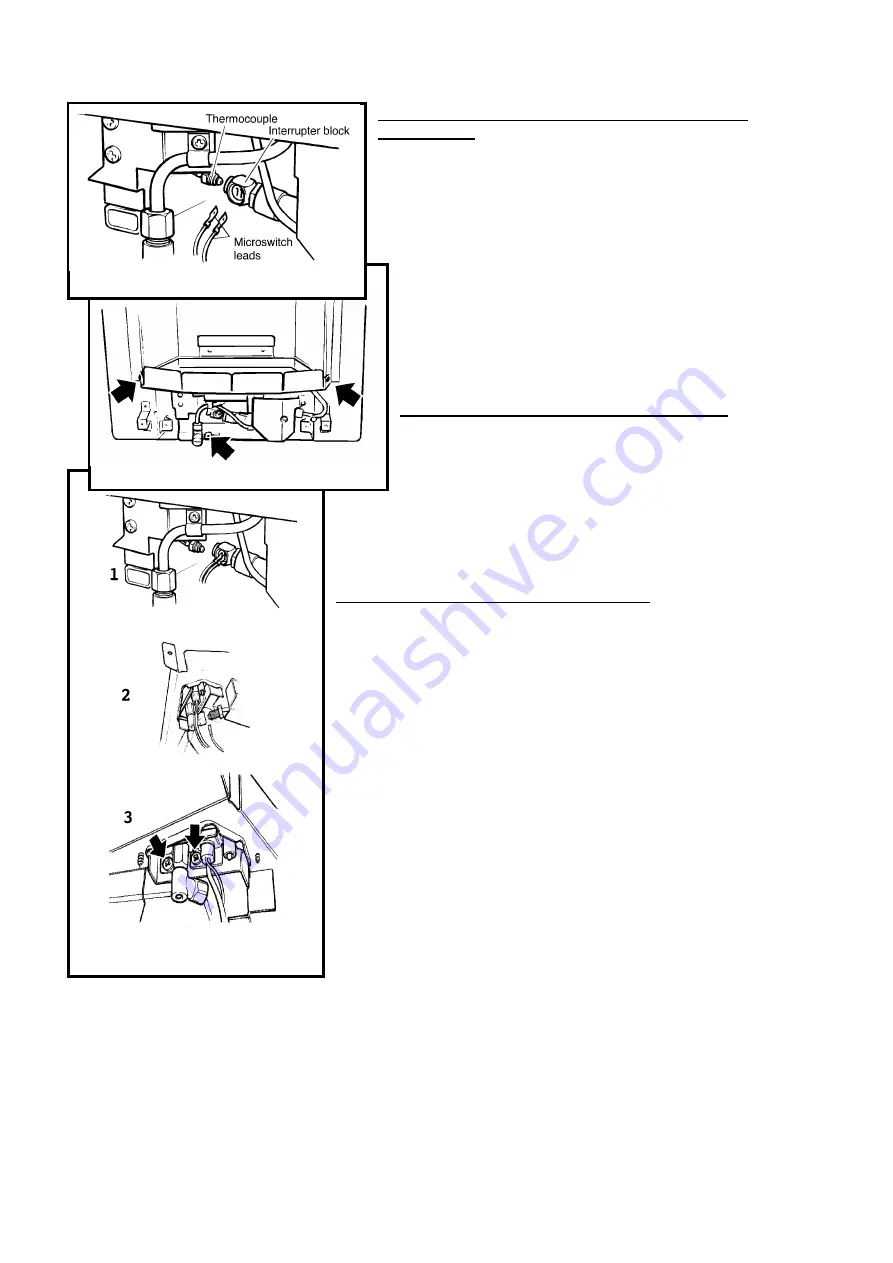
     To remove the thermocouple interrupter block

(see figure 44)

13.7.1

Remove the bottom front cover

13.7.2

Detach the thermocouple from the interrupter block by

unscrewing the thermocouple nut.

13.7.3

Detach the two microswitch leads from the interrupter block.

13.7.4

Remove the interrupter block by unscrewing from the gas shut-

off tap.

13.7.5

Refit in the reverse order. If the microswitch leads cannot be

easily attached to the interrupter block when it is fully tightened to
the gas shut-off tap, slacken it and rotate to allow the leads to be
fitted. Retighten making sure that the leads remain in place in the
interrupter block. Fit and tighten the thermocouple nut making sure
that the leads are secured in the interrupter block to give a good
electrical contact.

13.8     

To remove the burner unit (see figure 45)

13.8.1

Remove the front surround unit- See section 13.3.

13.8.2

Remove the 7 loose coals, the front coal halves, the base coal,

ceramic side walls and rear wall.

13.8.3

Support the inlet isolating elbow to avoid straining the

pipework and disconnect the appliance from the elbow.

13.8.4

Detach the burner unit from the convection box by removing 3 screws.

13.8.5

Replace in the reverse order. See section 13. 3. 6 for refitting the

surround.

13.9     

To remove the pilot unit (see figure 46)

13.9.1

Remove the burner unit - See section 13.8.

13.9.2

To give clear access for disconnecting the pilot pipe, detach the ignition

generator & bracket unit from the burner as described in section 13.6. and lift it
clear.

13.9.3

Detach the thermocouple from the interrupter block by unscrewing the

thermocouple nut.

13.9.4

Detach the electrode lead from the underside of the electrode tab.

13.9.5

Disconnect the pilot pipe from the pilot unit elbow.

13.9.6

Remove the first screw

 s

ecuring the dust cage to the


pilot unit / burner.

Carefully remove the dust cage and place aside.

13.9.7

Remove the second screw securing the


pilot unit to the burner.

Remove the pilot unit and place it aside.

13.9.8

Refit in the reverse order. See section 13. 3. 6 for refitting the surround.


Note 1 The pilot unit must be replaced as a whole assembly. Its individual components

are not separately replaceable.

2. Once removed, ensure that the dust cage is cleaned before refitting. Make sure

that it locates squarely onto the pilot unit without any gaps between the cage edges and the

pilot unit.

3. When the thermocouple is removed from the interrupter block, the microswitch

lead terminals in the interrupter block will be loose. Make sure that they are properly

secured to give a good electrical contact when retightening the thermocouple nut.


 Fig. 46 Pilot unit removal (Dust cage
not shown for clarity)

 Fig. 45 Burner removal points

 Fig. 44 Thermocouple interrupter block

Summary of Contents for 4190

Page 1: ...NaturalGas MODEL4191 ForPropaneGas I n s e t L i v e F u e l E f f e c t G a s F i r e s with U l t i m a t e F i r e s l i d e or F u s i o n Front I N S T A L L E R G U I D E Please keep in a safe p...

Page 2: ...e will be pleased to help Please telephone 0345 626341 Local call rates apply P l e a s e l e a v e t h i s I n s t a l l e r G u i d e w i t h t h e u s e r Model 4190 is for use with natural gas G20...

Page 3: ...ation 17 Operating Checks 20 Fire Control Check 20 Reference Pressure Check 21 Spillage Check 21 Final Review 22 Servicing Parts Replacement 23 Ignition Microswitch 23 Gas Shut off Microswitch 23 Fire...

Page 4: ...and is visible when the bottom front cover is removed Model 4190 Model 4191 Gas Natural G20 Propane G31 Inlet Pressure 20mbar 37mbar Input Max Gross 6 0kW 20 500Btu h 6 1kW 20 800Btu h Input Min Gross...

Page 5: ...ns of BS1289 as well as the current edition The flue blocks must have a minimum width not less than 63mm and a cross sectional area not less than 13 000mm2 Older editions of BS1289 required a cross se...

Page 6: ...o a purpose made proprietary class O 150 C surround The hearth material must be at least 12mm thick The periphery of the hearth or fender should be at least 50mm above floor level to discourage the pl...

Page 7: ...lation for the appliance is taken if it does not affect the safe performance of the appliance Note the spillage test requirements detailed further on in this manual If the fan is likely to affect the...

Page 8: ...Woodscrews 2 Fire retaining cables 2 Cable clamps 4 Eyebolts 1 Knurled shoulder screw for control linkage fixing 1 Installation template 1 Battery 1 Smoke match tube 2 Machine screws for front surrou...

Page 9: ...trol pivot bracket clockwise as far as it will go see figure 6 This should close the ignition circuit Sparks should be seen tracking from the electrode pin to the thermocouple tip see figure 7 If ther...

Page 10: ...d in section 7 of this manual Before selecting the retention method consult with the customer Method 2 is provided for instances where drilling holes in the front surface of the fireplace surround is...

Page 11: ...area Note that the areas are different for fireplaces with conventional brick flues and precast flues 5 1 2 Place the template on the fireplace floor printed side upward with the front line level with...

Page 12: ...e pipe If the hole is larger than the pipe seal it with tape Do not pierce the seal unless the supply pipe is to pass through it 6 4 The appliance is supplied fitted with a flue restrictor see figure...

Page 13: ...sing a no 12 masonry drill The holes should be equidistant each side of the centre line of the fireplace to ensure that the appliance finishes centrally in the opening when tension is applied to the c...

Page 14: ...en the cable retainers 7 2 12 If the convection box is not correctly aligned release the tension on the cables by slackening the screws and turning the hexagonal adjusters fully anticlockwise The conv...

Page 15: ...ltaneously open the gas tap allowing the gas to flow to the pilot Wait a few seconds while the air is purged The electronically generated sparks should light the pilot The pilot should then light the...

Page 16: ...control linkage Carefully slide the control button downwards while feeding the bottom of the control linkage through the gap between the surround fixing bracket and the burner supply pipe see figure...

Page 17: ...flat against the rear of the fire box See figure 24 10 2 Place the two halves of the front base coal in the burner compartment so that they rest on the ledges at the sides and front Pull the coals for...

Page 18: ...are marked at the rear bottom corners L Left side R Right side Place the side walls against the sides of the fire box and in the recesses at the sides of the base coals The markings L R should be at...

Page 19: ...e them in the central two valleys of the front coal See figure 28 10 5 2 Place two of the remaining coals in the two outer valleys of the front coal One each side of the large coals See figure 29 Plac...

Page 20: ...e burner should ignite at its lowest setting within 4 seconds of the pilot igniting Keep at this position for a further 10 seconds to allow the pilot flame to stabilise 11 1 4 Release the button The b...

Page 21: ...tside surface of the edge of the cross member figure 33 Plain steel tubes Insert the tube so that the neck of its flared end touches the inside surface of the edge of the cross member figure 33 Keepin...

Page 22: ...nder 12 6 Explain to the customer that the appliance has a flame failure spillage monitoring system Point out the explanation of this system shown in the users instructions under Operating the fire Ad...

Page 23: ...the electrode spark or pilot burner Check that soot or debris is not blocking any of the slots in the main burner After servicing make sure that the ceramic walls and coals are replaced correctly as...

Page 24: ...ntil it contacts the end of the spindle of the shut off tap 13 3 6 2 Pick up the outer surround and slide the control button upwards as far as it will go Make sure that the bottom of the linking bar i...

Page 25: ...See figure 41 Lift the slide unit clear 13 5A 3 Refit in the reverse order See section 13 3 6 for refitting the surround 13 5B To remove the control slide unit Fusion front 13 5B 1 Remove the surround...

Page 26: ...ve the pilot unit see figure 46 13 9 1 Remove the burner unit See section 13 8 13 9 2 To give clear access for disconnecting the pilot pipe detach the ignition generator bracket unit from the burner a...

Page 27: ...ured to give a good electrical contact See section 13 3 6 for refitting the surround 13 11 To remove the gas flow rate controller see figure 49 13 11 1 Remove the burner unit See 13 8 13 11 2 Detach t...

Page 28: ...eft squeezing the gasket between the two plaques Any gap should be between the right side of the plaque and the right side retaining flange 13 13 7 Fit the front and rear plaque clamping strips Make s...

Page 29: ...Natural Gas Appliances 1 566239 Injector Elbow type Bray cat 82 size 190 For Propane Gas Appliances 566939 H Igniter unit 1 554949 J Burner plaque gasket set For Natural Gas Appliances 1 545989 Burner...

Page 30: ...ds Valor is a member of the Society of British Gas Industries which works to ensure high standards of safety quality and performance Careful Installation Valor is a Corgi registered company All our ga...

Reviews: