background image

Page 49 


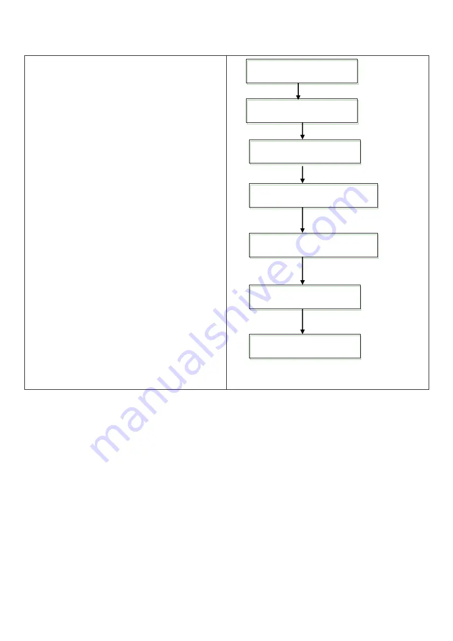
2: The method to replace IBT transfer cleaning component


1. On control panel, press <down> and <OK> keys at the 

same time, and it will show [consumables menu]. 


2. Press <down> till it shows [rest counter]. 


3. Press <right> or <OK> to select and show [fuser unit]. 


4. Press <down> to show [transfer belt cleaning 

component]. 


5. Press <right> or <OK> key to select 


6. Press <OK>key. 


7. Thus the IBT belt cleaning component counter is reset. 


8. Press <specification setting> to close the menu. 


Consumables menu 
Machine No. 

Consumables menu 
Reset counter 

Reset counter 
Fuser unit 

Reset counter  
Transfer belt cleaning component 

Transfer belt cleaning component 
Press <OK> to reset 

Resetting transfer belt 
cleaning component 

Transfer belt cleaning 
component reset 

Summary of Contents for VP-320C

Page 1: ...Page 1 User Manual Please read this manual carefully before using the equipment Valloy Incorporation 2018 04 Version...

Page 2: ...or Intel Core i7 3930K 3 20GHz RAM 12GB or greater HDD 150GB SATA 10K RPM OS Windows 7 Professional or Ultimate 64 bit Windows 10 Professional or Ultimate 64 bit Before installing the software please...

Page 3: ...eplace IBT belt cleaning component 33 8 6 Replace secondary transfer bias component 34 8 7 Replace IBT component or belt 35 8 8 Replace developer or developer unit 38 Chapter IX Restoration Method aft...

Page 4: ...portation by crane only one person is allowed to operate 3 In case of transportation by crane no one is allowed to stand under or near the machine 4 During transportation installation or cleaning proc...

Page 5: ...and repair 1 Before maintenance or inspection please turn off the main power 2 If power on maintenance or inspection is necessary it must be done by authorized electrical technicians 3 No one is allow...

Page 6: ...use death or injuries It indicates high warning degree Warning It warns the user that if this information is ignored causing error operation it may cause death or injuries Attention It warns the user...

Page 7: ...ny cause damage to the power causing electric shock or fire If the machine is not in use for a long time please unplug the power cable from the socket Otherwise it may cause fire During operation do n...

Page 8: ...5 m 2 6 Electrical specifications 1 The voltage for this machine is single phase 220V 50 60Hz 2 4 Installation steps 1 Put the machine one a flat ground 2 Use a pallet jack to lift the machine and pu...

Page 9: ...ood bad and paper box 3 2 System parameters Machine model VP 320C label printing machine Max output label paper roll Outer diameter 450MM Label paper width range 140 320MM Max print width 304MM Max pr...

Page 10: ...ponents Data port Caster Engine panel Secondary power Emergency switch Main control system panel Alarm light Web guide system Unwinding tension Air line connector 8MM Unwinding air shaft Rewinding sha...

Page 11: ...oor A Pass the engine door A and cooling system see Picture 4 4 in the print engine along the red path Close the engine door A in the side door not too tightly and pass the material to the tension sys...

Page 12: ...r till the material is straight The original installation position must be precise to prevent inclination and the tension shall be adjusted Close engine door A and turn on main power for the engine se...

Page 13: ...card verification function it will display the verified user identification for about 2 seconds In save power mode there will be nothing on the screen even when the printer is powered on 6 save power...

Page 14: ...s key is also used to print report list 13 return key In menu page press this key to return the last page 14 Overview In case of any error it is used to identify the indicated position in the error me...

Page 15: ...ill close and the rewinding length is reset to zero Rewinding roll loading Click it for rewinding roll replacement The tension and air shaft will open Setting System setting see Item 2 Clear alarm Cli...

Page 16: ...s paused Status Pause No paper There is no paper on the feeding shaft Status No paper Rewinding limit reached The rewinding shaft is full Status Rewinding limit reached Feeding paper unloading The sta...

Page 17: ...winding error Tracking error Tracking of the secondary tracking sensor fails Status ER003 Tracking error Cooling water alarm External cooling water machine alarm optional Status ER004 Cooling water al...

Page 18: ...it shows manual Press OK to confirm your selection If it shows 000 000 000 000 please go to step 8 7 Press left or return to return to the IP address obtain method Press down to show IP address Press...

Page 19: ...he whole LUP includes the following software 1 Adobe Reader XI 11 0 2 2 gs920w32 exe 3 install bat 4 FontPack11009_XtdAlf_Lang 5 LPUInstaller see Picture 6 2 6 3 6 2 1 Install Adobe Reader XI 11 0 2 D...

Page 20: ...Double click the Adobe Reader XI icon and click next according to the wizard till the installation is completed 6 2 3 Install install bat In the PDFColorCounter folder right click the install icon Ru...

Page 21: ...system will complete installation automatically 6 2 4 Install FontPack11009_XtdAlf_Lang Double click FontPack11009_XtdAlf_Lang icon and click next according to the wizard till the installation is comp...

Page 22: ...Page 22 Install LPUInstaller Double click LPUInstaller icon and click next according to the wizard 6 2 6 Input the set IP address on the engine control panel 6 2 7...

Page 23: ...er installation of AdobeReaderXI initialization is required before use and the default open method for printing data shall be Adobe Open any PDF file to set as follows Actual Choose paper source by PD...

Page 24: ...of the printer on the main interface 6 4 3 Basic setting and network setting before the use of the printer 6 4 4 Input the IP address in use in the network setting window 6 4 5 Select printer in the m...

Page 25: ...r 6 4 9 Input customized information of the material and select corresponding paper thickness and relate it with relevant ICC document Click OK to complete material adding Note See P48 for instruction...

Page 26: ...e 6 4 13 Click space setting to enter the page space setting page and review change current page space value 6 4 14 The default min page space is 2mm Click OK to send the setting to the printer and it...

Page 27: ...used for large file and multi page mode when the engine server processes slowly causing larger page space In case of single page file disable page space protection mode and print directly Note When th...

Page 28: ...sensor shall be turned on through the main system control panel See P52 for detailed use method of relevant sensor 7 3 Before printing one must select the corresponding material Click select to open t...

Page 29: ...he file to the printer 7 7 Click cost report and it will appear in a text box The PDF file displayed in the work will be calculated independently and the total costs of all works will show at the last...

Page 30: ...the file will be stored in the engine server and print after 5 minutes delay Within 5 minutes after transmission you can also start printing on the engine control panel The operations are as follows...

Page 31: ...o not shake or hit the used toner cartridge to prevent spilling of residual ink The ink powder is no harmful to human body If it is on your hand or clothes please wash it off We recommend you to use u...

Page 32: ...ce life and it will show this information Although you can continue printing for a period of time but we cannot guarantee the printing quality We recommend you to replace the new photosensitive drum 1...

Page 33: ...it out of the machine Take a new one from the box 8 2 6 Inset the two prongs on the front of the photosensitive drum with protection film to the hold on the machine as is showed in the picture 8 2 7...

Page 34: ...place the waste toner box according to the following steps Important Make sure the power is on when replacing the waste toner box When replacing the waste toner box the ink may be spilled to the floor...

Page 35: ...er in the cleaner may cause powder explosion due to electrical sparkle Do not throw the toner cartridge into open flame The residual ink powder in the cartridge may cause fire resulting in burn or exp...

Page 36: ...at the fuser unit has reached the end of their service life but can still be used then you can reset the counter directly 1 The amount of the printing pages of each consumable varies with actual print...

Page 37: ...that the component has reached the end of its service life but can still be used then you can reset the counter directly 8 4 5 Hold the fuser unit with one hand and fasten the screws on both sides wit...

Page 38: ...ent has reached the end of its service life but can still be used then you can reset the counter directly 8 5 5 Take a new IBT belt cleaning component and inset it into the printer 8 5 6 Press the kno...

Page 39: ...h the surface of the photosensitive drum with your hands Do not touch the surface of the IBT belt with your hands 8 6 3 Take the secondary transfer bias component out 8 6 4 Install a new secondary tra...

Page 40: ...dles and pull the IBT transfer components to the direction of the arrow 8 7 8 Hold the Front Rear handles to pull the IBT transfer component out 8 7 9 Hold the IBT transfer component with one hand and...

Page 41: ...he screws 2 remove the tension plate For belt replacement skip this step 8 7 13 When replacing the whole component 1 install the tension plate 2 fasten the screw For belt replacement skip this step 8...

Page 42: ...Before replacing the developer or the developer unit please pull the toner cartridge and waste toner box out remove IBT belt cleaning component and IBT component When removing the photosensitive drum...

Page 43: ...ew 2 Remove the front and front cover together 8 8 3 1 Disconnect the connector 2 Remove the screw 3 remove fan pipe 4 remove cable binding 8 8 4 1 Release cables 2 disconnect the connector 8 8 5 1 Re...

Page 44: ...he waste toner box is closed Confirm this also during installation 8 8 9 1 Remove the screw 2 Remove the wall panel 8 8 10 1 Pull the connecting piece on the developing room inlet 2 Lift the lower pow...

Page 45: ...to be installed and set the DC950 ATC sensor For the replaced developer make DC949 beginning developer ATC setting Enter the diagnosis mode press HFSI counter initialize to reset the HFSI counter Chai...

Page 46: ...formly 8 8 22 The distance between the developer and the installation slot on the top cover shall not be larger than 3mm 8 8 23 Neither the developer nor the ink powder shall be on the position showed...

Page 47: ...Link 954 834 Y See P47 for details 8 8 25 Reverse the developer unit to confirm the following issue The Neither the developer or the ink powder shall be on the position of DRS Block showed in the pic...

Page 48: ...nter on the control panel 1 On control panel press down and OK keys and it will show consumables menu 2 Press down till it shows rest counter 3 Press right or OK to select and show fuser unit 4 Press...

Page 49: ...to show transfer belt cleaning component 5 Press right or OK key to select 6 Press OK key 7 Thus the IBT belt cleaning component counter is reset 8 Press specification setting to close the menu Consu...

Page 50: ...o select and show fuser unit 4 Press down to show transfer component 5 Press right or OK key to select 6 Press OK key 7 Thus the transfer component counter is reset 8 Press specification setting to cl...

Page 51: ...30000 Operation times of IBT CLN Unit PV conversion 100 210mm 954 830 20000 480000 20000 Y developer unit using PV 954 831 20000 480000 20000 M developer unit using PV 954 832 20000 480000 20000 C de...

Page 52: ...use up or down to input the value of the new developer unit into the dialog box For example if you input Y30 and it will show Y 30 1024 007 7 Press OK to finish input 8 Press left key to return to DC...

Page 53: ...rrect and the fault still exists then the image transmission voltage may be incorrect In such case please follow below steps and adjust the voltage value There is white spot on the image lower voltage...

Page 54: ...correction of text and other high definition image Photo priority type is used for color level correction of pictures and photos with color gradient and other images with smooth color gradient 1 Press...

Page 55: ...fter inputing the adjustment value press OK to apply the setting 14 If you want to adjust the chroma of other colors please use return to return to step 9 and continue the other steps After setting pr...

Page 56: ...olor cartridge 70000 pages 7000 0 1 Fuser unit 480000 pages 48000 0 1 Black developer 480000 pages 48000 0 1 Color developer 480000 pages 48000 0 1 Waste toner box 26000 pages 2600 0 1 Material 10 IBT...

Page 57: ...button to finish the setting which is very simple Working status indicator light ON button OFF button 1 Put the light source on the color symbol and press ON 2 Remove the light source to set color and...

Page 58: ...unt of printing and special use may need more frequent maintenance Comprehensive maintenance task Interval Daily Cycle Monthly Annually Must Print head Cleaning Wipe Wipe Toner cartridge Check Wipe Tr...

Page 59: ...1 1 4 Take the cleaning stick sealed in the LED print head slowly out and the cleaning stick is located at the cleaning kit right under the photosensitive drum R1 R2 R3 or R4 11 1 5 Put the cleaning b...

Page 60: ...he belt taken out flat on a table and do not touch the surface of the belt with your hand 11 3 2 Turn the gear till the dust free cloth with ethyl alcohol wipe the dirty spots on the belt off Do not l...

Page 61: ...material type 2 Change material 3 The fuser unit is worn or damaged The color distribution is not uniform Toner cartridge worn out Powder feeding of two sides of the developer unit is not uniform The...

Page 62: ...is on 116 354 Hard disk reading failure Reformatting hard disk 1 Turn off the main power of the engine 2 Turn on the secondary power 3 Press up down save power keys on the engine panel at the same tim...

Page 63: ...ty period is borne by Vorey D Within the warranty period users shall follow operation guidance strictly to make relevant operations Vorey does not bear warranty responsibilities to the consequences ca...

Reviews: