8
9.
Slip one ¼” flat washer over each stud, and thread a ¼” – 20 kep nut onto each
stud. Tighten the nuts by hand to secure the housing, then secure them in an
alternating “X” pattern using the 7/16” socket (you will fully tighten them later, but
this is to keep the housing in place during mounting).
10.
Rotate the assembled unit, now with the housing secured to the mounting tubes,
into the upright position.
11.
Cut the wire tie securing the excess wire to the overhead housing. Feed the wire
through the housing and down the male end overhead tube. Once the wires are fed
through the tube, pull them through the opening at the bottom.
12.
On a new table, cut the cable tie securing the side mount display extension
harness and feed that harness into the table. On an older table, feed that harness as
far as possible through the opening and secure it for access in a later step.
13.
Have the remaining four ¼” – 20 x 1” pan head Phillips screws and mounting
bracket clamp ready at the backside of the table. You will need them in step #16.
14.
New tables have a trap door underneath the table. Remove it at this time
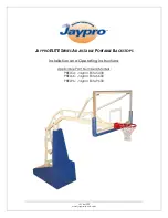
15.
This is where having the second
person to help gets important: Carry
the completely assembled unit to
the table. Aim the overhead so the
male tube, where the wire harness
exits, is positioned at the back side
of the table away from the service
door. Lower the female end into the
bracket and clamp installed in the
front side of the table during step
#3.
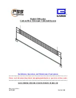
16.
With one person holding the
male tube of the overhead
assembly, have the other person
feed the wires from the overhead
through the opening in the mounting
bracket clamp. On new
installations, also feed these wires
into the back side of the table.
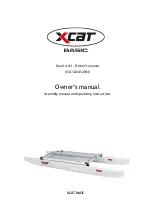
17.
Once the wire harness is in
place, use the four ¼” – 20 x 1” pan
head Phillips screws to secure the
mounting bracket clamp and
mounting bracket to the backside of the table.
Summary of Contents for Dynamo Hockey
Page 1: ......